


How Photograph Flowers Splashing in Milk with an Infrared Laser
Apr 6, 2019
Dunja Đuđić Kalinin
Dunja Djudjic is a multi-talented artist based in Novi Sad, Serbia. With 15 years of experience as a photographer, she specializes in capturing the beauty of nature, travel, concerts, and fine art. In addition to her photography, Dunja also expresses her creativity through writing, embroidery, and jewelry making.
Share:

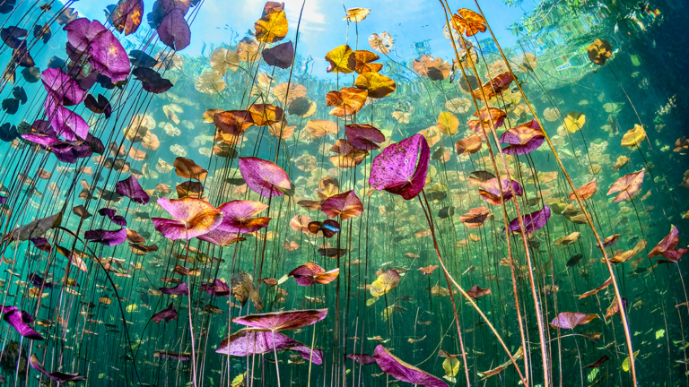
My Students came up with an idea to drop flowers into a pan of milk after they saw several pictures on Instagram. The students decided to create a technique for getting the perfect picture by eliminating all trial and error. The students created the following technique and were able to photograph over 70 photos, successfully capturing the splash every time.


To capture the splashing flowers, the camera was set to bulb mode in a dark room and the timing was controlled by an Arduino microprocessor. The Arduino detected the flowers breaking an infrared (IR) laser beam. An IR laser was used so that the laser would not have to be turned off when the image was made. If a red laser was used, the laser would have to be turned off before the shutter was opened.
An IR laser was also used in this photoshoot to give the students experience aligning a laser they cannot see with their eyes. The IR laser was detected by a phototransistor that was read by an analog input on the Arduino. The IR laser was not exactly matched to the peak sensitivity of the phototransistor so the analog input turned out to be a good way to detect the laser beam being broken.
Once the flowers break the laser beam, the Arduino delayed the flash trigger by 65 milliseconds. This timing was critical to give the milk time to splash. The action was frozen by an Einstein 640 ws flash set to 5.7ws which was a little above the 128 power setting. This setting was fast enough to stop the splash, but was able to give enough light.
The flash was placed below a diffuser panel and the pan of milk. The students also held light reflectors to give more light to the flowers. The milk was regular 2% milk, but was thinned out by diluting with an equal part tap water. The flowers were held horizontally about 8 inches from the milk pan. Once the camera’s shutter was opened, the flowers passed though the IR beam and the Arduino waited 65 milliseconds to trigger the flash. After the flash trigger, the Arduino went into a pause mode for 5 seconds. This pause mode was important to keep milk splatter from triggering the flash a second time in the exposure.
The students controlled the camera via tether while another student moved the flowers. This technique allowed for multiple shots to be taken in quick succession with relative ease. The laser beam must be properly aligned with the detector in order for the trigger to work correctly. The laser was taped to a tripod, and set to be an inch above the surface of the milk. The phototransistor was taped to a second tripod across the table. The tripods allowed for easy alignment of the laser beam. Once aligned, the beam between the emitter and detector can be used as a trigger. When the beam is broken, the flash triggers. The laser used in this system has a wavelength of 780 nanometers which is beyond the range of colors that that human vision can see. Here is a diagram of what the setup looked like:


The circuit schematic is shown below:

circuit is very important for alignment of a beam that is invisible to the human eye.
The Arduino Program:
Arduino programming specifics: The program starts with the setup function, which declares that an LED and a flash are going to be used as outputs and sets them both to go off when the laser is broken. The LED is for testing whether the IR sensor is working and the flash is used to light the image. The void loop() function, which is continuously repeated, is set up so that whenever the IR detector is reading at less than a 120 analog read value, the LED and flash are turned on and then off. The LED and flash are only on for 10 milliseconds. Afterwards, there is a delay for 5 seconds to make sure the flash does not repeatedly go off immediately. Here is the exact code the students wrote for the shoot:
/**IRLaserTimingForFlowers.ino
*
* Authors Morgan Ravenscroft, Stephen Rinaldo, Ashley Crichton, Tyler Wolstenholme, Patrick Damiano. Danny Heitmann, Kristina Kaszei
* Date created: 2/11/2019
*/
#define LED 11 //led is on pin 5
#define analogPin 3 //reading from phototransistor on analog pin 3
#define flashPin 10
const int flashTime=5000;// time it will wait before the next flash
const int pauseTime =10; //time it will wait between checks and between turning flash on and off
const int afterPass =65; //time between the IR laser being broken and the flash being fired in milliseconds
int val; //integer value called val used to read analog pin 3
void setup() {
pinMode(LED, OUTPUT); //Tells that pin 5 is used for an output
pinMode(flashPin, OUTPUT); //Sets the flash pin as an output
digitalWrite(LED, LOW); //Keeps LED off at start
digitalWrite(flashPin, LOW); //Flash starts off
}
void loop() { //Put your main code here, to run repeatedly:
val=analogRead(analogPin); //Analog reads val from 0:1024 on analog pin 3
if (val<=120){ //If the analog pin is read to be less than 120
delay(afterPass); //Delays for a time after the subject passes the infra red
digitalWrite(LED, HIGH); //Turns on led
digitalWrite(flashPin, HIGH); //Activates flash
delay(pauseTime); //Keeps led on
digitalWrite(LED, LOW); //Turns LED off
digitalWrite(flashPin, LOW);//Sets flash to be ready to activate
delay(flashTime); //Delays to allow for flash not to go off repeatedly
}
delay(pauseTime); //Delays to allow for read to be reset
}

The students had a lot of fun working on this shoot and hope the reader will be inspired to try their own images.

Materials used in this project:
- 780 nanometers IR laser obtained from Amazon (about $5.00 each)
- Arduino Uno microprocessor https://www.adafruit.com
- 330 ohm resisters
- Color LEDs (5mm dia.)
- Opto-Isolator: TLP 3042
- IR phototransistor (SKU: EC-010403) 10 for $1.00 from https://www.yourduino.com
About the Author
Ted Kinsman has worked as an optical engineer, a physicist, and a physics instructor before joining RIT to teach the technical side of imaging. Kinsman teaches classes in photographic instrumentation where students control cameras with micro-processors, a high-speed imaging class where students photograph bullets in flight, and a class on scanning electron microscopes. He has published numerous articles and books.

Dunja Đuđić Kalinin
Dunja Djudjic is a multi-talented artist based in Novi Sad, Serbia. With 15 years of experience as a photographer, she specializes in capturing the beauty of nature, travel, concerts, and fine art. In addition to her photography, Dunja also expresses her creativity through writing, embroidery, and jewelry making.


Join the Discussion
DIYP Comment Policy
Be nice, be on-topic, no personal information or flames.
One response to “How Photograph Flowers Splashing in Milk with an Infrared Laser”
מעניין מאוד,