


How To Build A Flash (With An Optical Slave)
Dec 28, 2011
Udi Tirosh
Udi Tirosh is an entrepreneur, photography inventor, journalist, educator, and writer based in Israel. With over 25 years of experience in the photo-video industry, Udi has built and sold several photography-related brands. Udi has a double degree in mass media communications and computer science.
Share:

Usually where danger is involved we simply say something like “please know what you’re doing” or “If you need to ask how this is done, this is not for you”, but for this particular piece, I thought a bigger warning should be in place. And I darn well mean it.
WARNING: This article involves dealing with High Voltage, up to 300v, which is stored in big capacitors. THIS VOLTAGE CAN KILL YOU. Never touch any of the components and always discharge the capacitor before working on it. Always keep in a well insulated project enclosure.
BY FOLLOWING THESE INSTRUCTIONS YOU AGREE TO BE THE ONLY RESPONSIBLE FOR ANY DAMAGE THAT MIGHT BE CAUSED BY DOING SO. WORK CAREFULLY AND FOLLOW WARNINGS.
If you think this warning was not bold, big or strong enough, please read it again. (I do realize this may end up in a loop for folks who think this is as easy as a learn how to solder project. That’s the point)
This article will help you understand the basics of how a flash circuit is working, and the second part will show you how to build your own optical triggered portable flash rated at 50 watt/seconds!
How Does A Flash Work In A Nutshell?
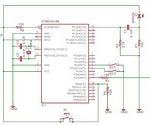
There really is no explanation of electronics without a scheme, so we placed a scheme below. While it does not go in depth about each of the parts it explains in a nut shell what’s its name and what it does. The magic of it, of course, is that you can create quite an effective burst of light, from a few 1.5V AA batteries.

The power from a low voltage battery (1) is fed into the inverter transformer (3) through a transistor (2), that is switching the current on-and-off, in a few Kilo-Hertz frequency (thousands of times per second).
The transformer (3) outputs high voltage of about 300 volts to a big capacitor (4) which will charge during a few seconds and serves as an energy storing device.
Meanwhile (as they say in comic books), the small trigger capacitor (5) is being charged. As soon as a burst of light is detected (from firing another flash) the photo-transistor (6) is translating the light-burst to a small voltage, that will trigger the Trigger Coil (7). The coil then produces a short pulse of very high voltage (6000 volts), which will ignite ionize the Xenon gas inside the Flash tube (8). Once ionized, it will draw all the energy stored in the big capacitor (4) and will output this energy in the form of light (the final flash).
What Are The Steps To Building A Strobe?
The first step is to go back and read the warning at the top of the post.
Then, start with deciding how much power (or how much light) you want your flash to output. Since the power to the flash tube is derived from the big capacitor (4 in the previous drawing), you control the power by controlling the size of that capacitor. Here is how to calculate the capacitor size.
As all things energy, flash output works kinda like exposure on P mode. You start with a base value for flash power, say 100w/s flash (or 100 Joules). To get this kind of flash you need to feed the bulb from a 2000uF capacitor at 330v.
Cut the capacitor in half, and you get half the power: a 1000uF capacitor will give you about 50w/s.
Actually, as a thumb rule, every 1000uF capacitor added will give you about 50w/s of energy.
Of course, once you have the power calculated you need to decide on a bulb capable on carrying that amount of power without exploding (yes Exploding).
Unlike incandescent lamps, flash tubes are rated for their MAXIMUM energy.
That means that a flash tube that is rated 200w/s MAX, can be fed with energy anywhere from 0 to 200 w/s. This exact lamp with a 1000uF capacitor will output 50w/s, and with FOUR(4) 1000uF capacitors will output 200w/s – its maximum allowed energy per flash.
So to recap, the capacitors are defining the flash energy, and the lamp has to have a compatible rating.
The rest are fixed components that have little dependency on the flash output which you wouldn’t have to change, we are listing them here as a reference.
We like to use the XFT-1610 as the inverter transformer, and TC-36 as trigger coil. They are very compact and always work great.
The following circuit diagram shows an exact basic circuit. It works reliably and gives good results, accepting 4xAA batteries as a portable power source, or a 5v transformer for external power, and delivering 50 w/s of light.

This basic circuit is great, because you can easily modify it – add more capacitors for higher flash power, change the flash tube to fit in reflectors, or even connect several flash tubes in parallel to place them in a circular reflector and create a Ring-flash.
Just a small reminder, the most important of course is, staying alive. Please take great care when trying to assemble this high voltage circuit.
After powering it, never touch any of the soldering or the components, always use an insulated plastic project box, and always use a volt meter to verify that the big capacitor is EMPTY before you are working on the circuit.
GOOD LUCK !
About The Author
Avner Richard is a fashion photographer and an electronics tinkerer. You can find his photography here, and his tinkering here.

Udi Tirosh
Udi Tirosh is an entrepreneur, photography inventor, journalist, educator, and writer based in Israel. With over 25 years of experience in the photo-video industry, Udi has built and sold several photography-related brands. Udi has a double degree in mass media communications and computer science.


Join the Discussion
DIYP Comment Policy
Be nice, be on-topic, no personal information or flames.
10 responses to “How To Build A Flash (With An Optical Slave)”
Fantastick article, is the prin available?
Hi,
thanks great article! This is a very interesting post for me. I have one question, how can I extend the circuit to have a variable flash energy? So may 100%, 50% and 25% of the flash energy. I think I have to add other capacitors but don’t know how.
I want to use a micro controller to enable different flash energy 100%, 50% and 25%.
So how can I extend this circuit to change the flash energy by micro controller?
How can I activate different capacitors by my micro controller?
Thanks for any help!
Hi,
its me again. Is there any reflector available that I can use this flash inside my DIY camera?
any suggestions on how to tweak the circuit to work on a large power source?
hey i cant find the transformer on element14, is there a different catalog name or is there an alternative i need the exact part number, please help!!!(and will a 300uF 450v capacitor work)
To convert to 220V You don’t need any additional cirquitry, just get rid of first 3 parts in cirquit diagram. All these parts do is converting DC to 220V AC anyway.
You could die if you try this. You’d need galvanic separation and current limiting and a fuse at least. Symmetric power usage would be nice, too.
That said, I’m not an electrician. A specialist might see even more problems.
But how do you connect this to a camera???
Hi, do you think it’s possible to create a remote, portable flash unit that straps to your wrist and has the head in the palm of your hand? Flash street photographers could use it to stay a bit more stealthy.
if I want to power this from a 12 volt battery, would I need to do anything besides change to an XFT-1934 transformer?