


Studio DIY: Disposable Camera Ring Flash
Mar 8, 2008
Udi Tirosh
Udi Tirosh is an entrepreneur, photography inventor, journalist, educator, and writer based in Israel. With over 25 years of experience in the photo-video industry, Udi has built and sold several photography-related brands. Udi has a double degree in mass media communications and computer science.
Share:
 Not too long ago, I have posted an article about making a strobe from a disposable camera. I was soon after that I called out to the great community of DIY photographers to make a disposable ringlight from such disposable camera strobes. And why not – they are cheap, available and do not require too much power.
In my mind there were three main challenges in making this project work: 1. Chaining the camera flash units; 2. Triggering the ringflash remotely; and 3. Powering the individual flash units.
Dave Ajax (Divet) from the DIYP Instructables group has risen to the challenge. Dave was also kind enough to allow me to post the full tutorial on this site, keeping the great tradition on DIYP Instructable projects like the Time Lapse Photography project, the Ingenious Camera Stabilizer and the Muslin Backdrop project.
Intro – Disposable Camera Ring Flash
Build a disposable camera ring flash. Disposable cameras are discarded after the film has been removed. Photo labs often have boxes of them under the counter, waiting to be recycled. If you ask nicely, you can often get more than enough to experiment with. Try to get at least six for this project, all of the same type.

Step 1 – Build It
Materials:
- 10″ Cookie tin
- 6″ Metal dog bowl (Dollar Store)
- Disposable cameras
- Radio Shack AA battery pack (with built in switch)
- RD616 wireless flash trigger ($20 Ebay – search: “flash trigger 16 channel wireless”)
- Surgical tubing
- Old tripod plate
- Broken door cloths hanger
- 3.5mm phone jack
- Packing Tape
- Velcro
- Wire
- Bolts
- Carl Vogt’s $5 Photo Slave:
- SCR 400 Volts 4 Amps (NTE5457 or Phillips C106D)
- 1 meg ohm 1/4 watt resistor
- .05uF 400 Volt capacitor
- Perf board
- Solar cell from a dollar store calculator (WARNING: Dollar stores often sell calculators with fake solar cells)
Tools:
- Nibbler (Radio Shack)
- Punch (or nail)
- Drill
- File
- Screwdriver
- Soldering iron
- Solder sucker
- Wire stripper
- Hot glue gun
- Multimeter
- Alligator clips

Schematics (note the photo slave at the center)
Step 2 – Open It Up
WARNING: A fully charged capacitor can give a good shock or burn. Do not touch the circuit board or the battery holder. Use the end of the large capacitor as a handle when working on the flash. Remove the battery from the bottom of the camera. Use a small screwdriver to cut any paper sealing the camera and to pry it open.
Short out the capacitor with the tip of a screw driver by touching both leads of the capacitor at the same time. Once the capacitor is discharged, there is less risk of being shocked. WEAR SAFETY GLASSES when shorting out the capacitor. There may be sparks. Getting hot solder in the eye is a life changing experience.
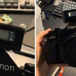
Foto Source disposable camera

Foto Source disposable camera

Touch screwdriver at base of capacitor. Wear safety glasses.
Step 3 – Flashes
Replace the flash trigger mechanism with wires. Use a solder sucker to remove the solder then push out the metal lever and knob with the tip of a hot soldering iron. Solder on a generous length of wire to each contact. They can be cut to size later.
There is also a simple pressure switch to turn on the flash. Push the metal prong with a nail until it is touching the board, and then solder it to both contact pads. Now the flash will always be on.

Flash PCB

A view of the flash trigger from the back.

Note the pads in the middle – this is where you solder the switch

Note the Soldered Switch and New wires installed
Step 4 – Testing
Often some of the flashes will be damaged. Test all of them with the RD616 wireless trigger using alligator clips and mark the ones that fire reliably. Refer to the wiring diagram for the proper connections. The RD616 is used instead of directly connecting the flash to the camera and risking damage from high voltage.

Left flash is triggered by the RD616. The other flash is fired by a slave. See wiring diagram for correct clip placement.
Step 5 – Slave
Build Carl Vogt’s slave using perf board and then test it with each of the flashes. If you are lucky all three flashes will run off of one slave, otherwise you will have to build several slaves. A soldered circuit is the best, so what doesn’t work with alligator clips, might work when the flashes are installed.

Schematics for Optical slave

Optical slave assembled
Step 6 – Cookie Tin
Mark a 3 1/2″ circle on the bottom of the metal dog bowl. Punch or drill a hole in the bowl and then use the nibbler to cut out the circle. Drill 4 bolt holes around the edge of the circle.
Place the bowl in the middle of the cookie tin. Mark all holes and drill or nibble to remove metal. Use a file to dull sharp edges.
I used an old plastic camera plate attached to a broken door cloth hanger to mount the camera, but any angle bracket will do. Drill holes and attach. Drill and install the 3.5 mm phone plug.
Cover bottom of cookie tin with several layers of clear packing tape to insulate the metal from touching the flash circuit boards.

Cookie Tin

Cookie tin with bowl

Camera Plate
Step 7 – AA Battery Pack
Rewire the AA battery pack so the batteries are in parallel, not in series. This will keep the voltage the same (1.5 volts) but increase the amps. Use a needle nose pliers, screw driver and a soldering gun to remove metal contact plates (spring and nipples). Cut the plates with tin snips and place all the springs on one side of the battery pack, and all the nipples on the other. Take a bare wire and solder all the nipple plates together. Then solder all the spring plates together with another wire. Attach the red wire to a nibble plate and the black wire to the switch. The switch in turn connects to a spring plate. Install batteries and test the voltage with a multimeter.
Drill a hole through the lid side of the battery pack and bolt it to one side of the cookie tin. Run the battery wires through another hole into the cookie tin.

Battery Pack opened

Battery Pack closed
Step 8 – Wiring
Solder wires from the battery clips of the most reliable flash to the external battery case. This flash will be the trigger flash. Hot glue the flash into position in cookie tin. Solder the trigger wires from the flash to the phone jack. Plug in the RD616 wireless trigger into the jack and test. Hot glue velcro to the outside of the cookie tin to hold the RD616 in place.
Hot glue the slave near the trigger flash. Solder the second flash to the slave and the battery pack and test. Do the same with the third and fourth flash.

Mounting with hot glue. Note – all three flashes are popped by one flash

Phone jack attached to trigger
And schematics again
Step 9 – Finish
When everything is working, bolt on the dog dish and camera mount. Split one side of the rubber tubing and cover the edges of the inner hole to protect the camera lens. At 8 feet you should get about F5.6@60 100 ASA. The slave will not work in bright sunlight, but it’s suitable for indoor use.

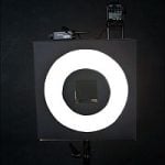
Bare cookie tin popping

Complete assembly

Rockin’ sample shot
Modifications:
Additional modifications could be adding 4 more flashes or making a wax paper diffuser for the front of the ring. If you don’t have a RD616, it might be possible to place the slave’s solar cell on the back of the cookie tin and use the camera’s built in flash to trigger all four lights. Use any leftover flashes to build a peanut butter jar strobe, a simple disposable camera slave.
Leftovers
So what do you do with any flashes left over from making the ring
flash? Building a couple of peanut butter jar strobes is an option. The
flash of one jar is controlled by a RD616, the other by a slave. The
flashes aren’t very powerful, but they are interesting to experiment
with.


More Great Projects:
– Create your own Bokeh
– DIY Homemade Reflector Stand
– Flash Mounted homemade DIY Softbox
– A Floor Lit Table Top Studio Project
– Just Fab’s Turkey Pan Beauty Dish

Udi Tirosh
Udi Tirosh is an entrepreneur, photography inventor, journalist, educator, and writer based in Israel. With over 25 years of experience in the photo-video industry, Udi has built and sold several photography-related brands. Udi has a double degree in mass media communications and computer science.


Join the Discussion
DIYP Comment Policy
Be nice, be on-topic, no personal information or flames.
2 responses to “Studio DIY: Disposable Camera Ring Flash”
I just went to my local drugstore camera developer and asked if they had any old used disposable cameras I could have. They said sure and gave me a couple of hundred of them! They usually turn them over to a company that recycles them, but they don’t get any money for them, so they were happy to let me have them. Easy source for these strobes if you want a lot (or just a couple) of them.
I’m producing a show where I’ll need fake photo flashes going off. I need these to be remotely activated on cue. Any chance of getting someone to make this for me?