


Build A Bluetooth GPS Unit For Nikon Cameras
Aug 15, 2012
Udi Tirosh
Udi Tirosh is an entrepreneur, photography inventor, journalist, educator, and writer based in Israel. With over 25 years of experience in the photo-video industry, Udi has built and sold several photography-related brands. Udi has a double degree in mass media communications and computer science.
Share:

From the first time I saw the power in geotagging images I was immediately hooked. My Nikon D90 is capable of geotagging, but, unlike the S100 (for example) it has no internal GPS and requires the somewhat pricy GP-1 GPS Unit. I set out to make a better cheaper solution.
I started by doing a lot of research on this topic and it turns out that there is a fairly simple way to connect a receiver to a Nikon camera. Simple, if you don’t mind a bit of makering :)
To keep the unit more mobile, I wanted to use a GPS that supports Bluetooth. This way I could have a less bulky setup. (+ I got to reuse a Bluetooth supporting GPS unit I already had). The nice bonus is that it works with any Android smartphone which has the “GPS over Bluetooth” application installed, you can download it on the Play Store.
There is definitely some hack and slash to this project as well as some soldering.
What You Will Need (Go eBay!)
- Remote Shutter Release Cord for Nikon MC-DC2 (I bought mine for D90 off eBay) – 3$
- Bluetooth Modem / Breakout to UART serial (RX/TX) (must have the AT mode) – 13$
- USB2.0 to RS232 TTL Converter Module PL2303 – 2.40$
- Bluetooth GPS receiver (bought mine for 30$ on DealExtreme)
- Project box (I bought a pills case)
- PC with USB port
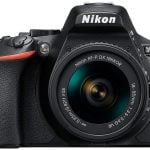
- Nikon camera
- Some soldering and electronics skills
1. Explanation About The Parts And Their Role
The Remote Shutter Release Cord for Nikon MC-DC2 was hacked into a Nikon Connector. It is an ugly hack but the cheapest I could find at about $2-3 on eBay. Take the shutter release box off and leave the wires with the connector.
Note You need to check the connector. It should have all the metal plates in there (8), some of the manufactures just make it with the Ground, Shutter and Focus pins only.

2. Bluetooth Modem / Breakout to UART serial (RX/TX) is the main part in the project, it give the possibility to “talk” to the Bluetooth GPS receiver. We will configure it to connect to a specific Bluetooth device.
")
In case you were wondering, here are the module pins, we’re gonna use this info in a bit.
- 3.3V – We will not use it
- VCC – The 5v pin (Power)
- GND – The ground pin (Power)
- RX – Receiving pin (Data in)
- TX – Transmitting pin (Data out)
3. USB2.0 to RS232 TTL Converter Module PL2303 will allow “talking” to the Bluetooth module and configure it. As you can see I am using the PL2303 chip and I had to put a Jumper between the 5V and the middle pin to select the appropriate voltage

The module pins:
- VDD – The 5v pin (Power)
- TXD – Transmitting pin (Data out)
- RXD – Receiving pin (Data in)
- GND – The ground pin (Power)
Second header:
- 5. 3.3V – We will not use it
- Middle volt pin – Need to be connected to pin 7 – the 5V
- 5.0V – Need to be connected to pin 6 – the middle one
Note that some of the USB module will not have the second part of the pins, in my case it exist to choose the volts.
4. Bluetooth GPS receiver receive the GPS signal (NMEA protocol) and transmit it over the Bluetooth.
Tearing Off The Cover Of The Connector
Take the Shutter Release box and open the screws. You will find 3 wires connected to 3 metal pieces. Separate the wires from the plates.

Now, carefully cut the connector cover until you see the wires and the connector itself.

3. Installing the USB to RS232 on your PC.
Now it is time to install the USB module on your PC. Installation is kinda specific to the module you bought, but in general you should install the drivers and a new com port should appear. As you can see my new port is called COM9

4. Connecting The Bluetooth Module To The USB Module
Remember them pins from the components review, this is where they come handy The list below shows you what goes where.
Right side USB module –> Left side Bluetooth module
- VDD (5v) –> VCC
- GND (Ground) –> GND
- TXD –> RX
- RXD –> TX

I installed a l little bridge on the Bluetooth module because the board had holes and it is easier to work with pins.
Be careful with the connections, if you mess it you can short and kill you modules and even your USB port.
5. Configuring the Bluetooth module.
The first thing you want to do is change the mode of the Bluetooth module to AT mode. AT mode allows sending commands to the Bluetooth module. You do this by switching the button to the left (the contacts side).

Now connect the USB module to your computer, you should see a LED light on the USB module and blinking LED on the Bluetooth module. The Bluetooth module LED have several blinking modes:
- The first is slow blinking (and light goes longer) which will appear in the AT mode.
- The second is fast blinking which says that the module is searching for devices.
- The third one is when the module is trying to connect to device it will show slower blinking than the searching mode but faster than the AT mode.
- The last one is when the module is connected, you will see two blinks and break.
To configure the module, open a terminal software (I use RealTerm which I got from the item’s page)
Set the Port and the BAUD to your baud rate (it supposed to be in the Bluetooth module manual) and click on Open.

Then got to the Send tab and tick the two first +CR and +LF in the EOL.
Now you can write your commands :)
To test it, write AT in the line and then click Send ASCII. If everything went right you will see a little OK in the terminal output.

The next part is to send the right commands to the Bluetooth module.
For example, if you want to change the module name type: AT+NAME=”yourname” and click Send ASCII, if it went right you will see OK again.
To check the name of the module type:
AT+NAME?
My output is:
+NAME:Nikon D90 Bluetooth GPS
OK
Now, let’s configure the Bluetooth module to work in master mode. This is what the command dialog should look like (responses in blue):
AT+ROLE?
+ROLE:0
AT+ROLE=1
AT+ROLE?
+ROLE:1
Now, we have to configure the password for pairing. I used 0000 because it’s my Bluetooth GPS receiver password and it can be configured also on my Android phone.
AT+PSWD=yourpassword
AT+PSWD?
+yourpassword
Now let’s set the baud rate for the Nikon camera:
AT+UART=4800,0,0
Next, we will set the connection mode, you can choose between 2 modes.
0: Specific address mode (the address is specified in binding command), 2: No specific address, the module will search for the nearest devices and will try to connect automatically (this mode is less secure)
If you want to choose specific address type: AT+CMODE=0 and set the MAC address with the following command: AT+BIND=1234,56,abcdef
Notice that the MAC address formatting somewhat weird, you have to change it. So if your address is: 00:02:B3:40:E0:A5 you will have to write: 0002,b3,40e0a5
If you don’t want to set it to specific address just type: AT+CMODE=2
Switch the AT button back to its original position.
6. Soldering The Wires To The Bt Module
There are 3 wires: Ground, Shutter and Focus.
Take the red (shutter) and the yellow (focus) out, don’t touch the white one, it’s placed right.
The red wire should be soldered to the 5V on the connector.
The yellow wire should be soldered to the GPS data on the connector.


If you think you’re not sure, take a look HERE and HERE.
On the Bluetooth module, solder the red wire (5v) to the VCC (5v), solder the yellow (GPS data) to the TX (Transmitting data) and the white (Ground) to the GND (Ground).
Be careful with the 5V and GND connection, if you connect it wrong you can burn your camera or something.
7. Testing And Done

Now connect your module to the camera and wait to the LED light to be turned on. If everything went as we wanted, you will see it blinking and connecting to your Bluetooth GPS receiver you camera will show blinking GPS icon. When your receiver get a fix go to GPS in your camera and hit Position-> and you get it!
Don’t forget to take it out from your camera when you done, it drains the battery even if your camera is off.
I used a small pill box for the camera end – a perfect fit.
Congratulations! you DONE!
I want to thank Eulalio Jimenez from https://www.photoleza.org for his help.
And also for Fernando Lamarca Belanche (aka FLA) from https://www.nikonistas.com.
Some Pictures Of The Final Product


About the Author
Ido Nassimi is a photographer and an electronics enthusiast based in Petach Tiqua, Israel. You can follow him on flickr and watch his portfolio here.

Udi Tirosh
Udi Tirosh is an entrepreneur, photography inventor, journalist, educator, and writer based in Israel. With over 25 years of experience in the photo-video industry, Udi has built and sold several photography-related brands. Udi has a double degree in mass media communications and computer science.

Join the Discussion
DIYP Comment Policy
Be nice, be on-topic, no personal information or flames.
2 responses to “Build A Bluetooth GPS Unit For Nikon Cameras”
i made it for my D90, works great. I upgrade to D7000, will the wiring setup be the same? In otherwords will it work on any nikon with this type plug
hey! if i want to use my android device with app like GPS over BT as gps reciever and slave bluetooth module HC-06 to transfer gps data on my nikon d90, that will be posible?