


Studio Lighting – DIY Cheap Soft Light Panel Frame Designed for Flash (or hotlight)
Mar 9, 2006
Udi Tirosh
Udi Tirosh is an entrepreneur, photography inventor, journalist, educator, and writer based in Israel. With over 25 years of experience in the photo-video industry, Udi has built and sold several photography-related brands. Udi has a double degree in mass media communications and computer science.
Share:
Soft light Panel Introduction
In the following article, Brian Zimmerman will demonstrate the construction of a soft light panel frame. As Brian will illustrate, the soft light panel frame can be used to reduce the harshness of light, and to crate soft eye pleasing picture. THe soft light panel can be used to take portrait pictures, or still life picture. The construction is not easy, but very rewarding.
Enjoy your build.
Soft light Panel Frame
This latest design uses the same 3×4′ nylon diffusion panel as the other design (see “Hotlight” album folder for construction details for the 3×4 panel), but here it is mounted on a single pole stand with a flash adapter frame attachment (Ripstop Nylon is Item number 263-7783 at Jo-Ann Fabrics, 60″ width @ 5.99/yard). I prefer this design over the other frame, because it is easier to set up, has fewer parts, and orients the panel horizontally to light a wider area (which also may give the option to shoot under the frame – about 5 ft max above floor). This design could be used with a hotlight as well as an ordinary hotshoe type flash unit or slave flash like the one illustrated here. One slight disadvantage is that the height of the panel is not as easily adjusted, although that is not often necessary and can still be accomplished by adding or removing extension sections to the frame hanger above the pivot joint as needed to achieve the desired height.
The following pictures used the 500W Halogen light behind diffusion panel to right plus foam core reflector to left and 250W light above left for hair.

Overall view
Overall view of the nearly 8 ft tall lighting stand showing slave flash activated by the camera’s flash. Note nylon cord tethered between the top and bottom of the frame to prevent bending of the main support under the weight of the panel frame hanging in front, similar to the manner in which a sailboat’s mast is supported. You may need a shorter vertical piece, depending upon ceiling height, but one of the nice things about this design is that you can always add sections to the main vertical piece using PVC couplers to achieve the desired height. Currently, I use two sections of approx 44″ length joined by a coupler (no glue, of course), since the base and top pieces add to the total height which must be less than 8 ft for a typical ceiling (carpeting reduces it further).

A closer view
Since this photo was taken, I have replaced the top horizontal hanger support (shown here with 1″ PVC) with 1-1/2″ PVC like the rest of the main frame, to make it a bit more rigid. The diffusion panel screen and flash support is framed with 3/4″ PVC. One advantage of hanging the panel in this orientation (versus vertically, as in the other stand design) is that the weight of the frame puts tension across the fabric to help keep it tight and flat. Ripstop Nylon is Item number 263-7783 at Jo-Ann Fabrics, 60″ width @ 5.99/yard

Details
Details showing how the soft panel frame is mounted to the main frame using the same slip T-joint described in the previous Hotlight Design. Note that sliding the frame inside the slip-T allows the panel to be adjusted to different angles. As the center of gravity shifts, the panel tilts and the angle changes by rotating on the cotter pin from which it is suspended and attached to the main frame. Also note that simply removing the cotter pin will detach that soft panel from the main supporting frame, and it can then be used separately or even hung from a ceiling. Extension tubes may be inserted at this joint to lower the height of the panel, if desired (see next photo). A 16″ lenght of tube with a coupler glued on the end, with holes drilled at each for the pins, plus another 8″ one can be used either by themselves or in combination to give a range of heights.

Extension tube used to lower the mounted height of the diffusion panel.

Frame adjusted to angle nearly straight down.

Frame angled to vertical position.

Closeup view showing the flash attachment support with a flash unit having a tilting head, mounted with the long dimension of the flash lamp parallel to the long axis of the soft panel screen for best light coverage. Flash is about 18″ behind the panel. Note that in this orientation the flash lamp is optimally positioned with respect to the screen to be illuminated, however this may not be true of the flash body housing the autoflash sensor. The autoflash sensor may not be reliable due to reflections from the brightly lit screen, so it’s probably best to use the flash only in manual mode at full power or dial in a power setting if available and control the exposure via aperture setting in the camera.

Another view showing flash fitted onto frame. Note the front of the flash extends just beyond the frame to avoid casting a shadow on the lighting panel. The two 45-degree couplers and T-coupling behind the flash have been glued together, but the rest are not glued to allow adjustments for positioning the flash.

Another view showing how the flash fits into the modified T-joint piece.

Details of T-joint modified to serve as a flash adapter. Part of the T was notched out with a small hand saw and a flat piece of plastic glued in place with PVC cement. The flash slides right into the groove in the flat plastic piece. For an easier mounting solution, see the next photo.

A hotshoe adpater mounted on a T-fitting. Hotshoe has a tripod socket on the bottom side, and a PC cord that is handy if the flash does not have an optical slave trigger built-in or you want to fire it directly from the camera’s hotshoe or PC connector.

View showing how the hotshoe is mounted using a 1/4″, 20 threads bolt passed through holes drilled through both sides & fastened with a nut inside the tube. Filing the surface of the T-coupler flat helps to keep the hotshoe from twisting loose.


Flash mounted on diffusion panel frame, along with a 75W halogen lamp for a modeling light. Note switch on cord of modeling light. It’s probably a good idea to set a custom white balance using a white card and the same lights to be used for your photos. This is particularly true if combining different light sources or using a nylon diffusion screen which could alter the color, depending on which fabric is chosen.

Closer view showing flash and modeling light mounting.

Modeling light assembly. PVC end cap holding light fixture fits snugly over a T-coupler if you use a thicker T with a threads inside. Electrical cord is passed through a hole drilled in the T and knotted on the inside, then connected to the socket wires with wire nuts and electrical tape.

Components of modeling light, including 75 Watt, 1130 lumens, wide angle (50°) quartz halogen flood lamp, 15′ cord, with socket mounted on a 3/4″ PVC cap (drill hole to fit). I found this peculiar extension cord with a switch on the end of it (designed to control the socket at the other end), so I replaced the switch with the light socket and moved the switch further down on the line, then replaced the plug with a new one.

Another lighting option showing a 500W halogen worklight (hotlight) attached to frame (one of the lamp brackets had to be bent to adapt to frame), and secured with two bolts.

Closer view of 500W halogen lamp mounted to frame.


Fresh Key Lime Pie.

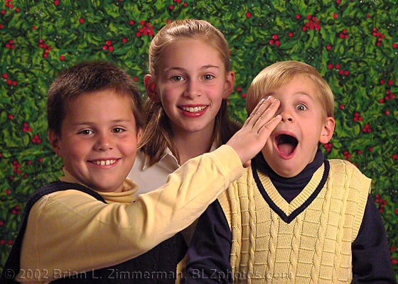
First test with real subject using slave flash/diffusion panel lighting with reflector and the new backdrop/stand. I’m not happy with the hair lighting (maybe should have moved it off to one side more), and I didn’t fix his shirt, plus he needs a haircut, but the lighting isn’t bad overall I think. I probably need to lower my main light a bit for better lighting of the eyes. (1/125 sec @ F3.2, 200mm, ISO 50) I plan to use only flash for main lighting of portraits and save the halogen worklight just for inanimate objects.

© 2002 Brian L. Zimmerman, BLZphotos.com

Udi Tirosh
Udi Tirosh is an entrepreneur, photography inventor, journalist, educator, and writer based in Israel. With over 25 years of experience in the photo-video industry, Udi has built and sold several photography-related brands. Udi has a double degree in mass media communications and computer science.


Join the Discussion
DIYP Comment Policy
Be nice, be on-topic, no personal information or flames.