


Variable 3 point LED lighting kit for macro/miniature for $55
Dec 15, 2014
Bimal Ramdoyal

We love it when our readers get in touch with us to share their stories. This article was contributed to DIYP by a member of our community. If you would like to contribute an article, please contact us here.
Share:

Welcome to my tutorial on how to make a 3 point light setup kit that allows you to vary the point LEDs independently. I wrote this for fun and i hope it inspires you! Warning: ManualMode.ca and I are not responsible for ANY damage caused to you, others or your household while following this tutorial.
I decided to make this kit because i shoot macro a lot and I’ve been disappointed by the macro mini studios i bought mostly because i could not control the light intensity for each bulb and even if I hacked it into a dimmable solution, fluorescent lights do not dimm, so i had to buy special white light tungsten bulb. I was also limited by size of the bulb and the heat it generated. All i wanted is to have positional whitelights that can vary their brightness and small enough so i can use it for macro.
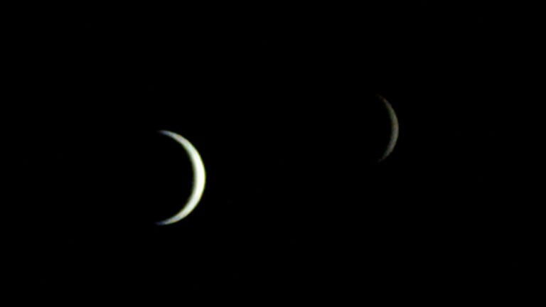
Before I dive in, look at the lead image to see some quick tests I made with the completed setup
These were achieved using the kit i am going to show you how to make.
Step 1: The schema and the parts list

The BS part shown above (4 resistor) is not a show stopper, my local electronic store ran out of 180O 1 watt resistor so to make 1 watt out of 4 x 0.25w resistor, i connected 4 x 680O ressitors in parallel, giving me about 170O at 1 watt which is good enough and wont burn. We need at least 1W for these because of the power dissipation and to prevent the resistors from burning.
I am going to show what the parts look like, so that if you want to try this and have basic knowledge of electronics, this can help you.

^ Potentiometers 1KO and knobs

^ You will need some RCA plugs male + female. The goal is to make the female outlets at the back of our box so we can plug in colored LEDs as well.

^ 12V 1A dc adapter and the power in adapter (that round thing).

^ 1 Watt White LED and some screws and nuts. Notice how the LED has markings for the +ve and -ve terminals.

^ Power transistor TIP31c. Reason why we are using this one is because if we want to modify this same circuit to use higher power LEDs 3-5 watts, these transistors will do fine, but might require a heatsink.
Step 2: Start putting everything together
Lets start by soldering at least 3 feet of speaker cable or any thin paired wire you have lying around, to the LEDs. First step, solder the wire to the RCA plug as shown below. Make sure to get color coded wire or you can mark it yourself. We wil assume the center pin of the RCA is +ve so the other end of this wire should be soldered to the + sign of the LED.


Repeat this for the other 2 LEDs and once soldered, you may put a touch of hot glue on the solder to make sure it holds. This is what it should look like, and then put away for now.

Next solder 2 color coded wires (use the hookup wire for breadboard/arduino projects, it makes life easier) to the female RCA sockets as shown below:


When assembled after soldering, the RCAs should look like this:

Next, solder a red and black wire to the power in adapter. (you will see it in the image at the top with the 12v DC adapter)

Next take a piece of pre-soldered PCB (i usually get the lined ones on the left but you can also use the one on the right with their own individual solder spot) and break 3 small pieces as shown. These will be soldered to the transistors and cables will run from them to the main circuit board.

Now solder the transistors to each of these boards. Please make sure you follow the orientation of the lined solder if you are using that type of PCB. To solder the transistor, look at the front face with the text on it, and solder as is.

Use 3 x 3 color coded cables and solder one on each of the left-most pin. Solder on the PCB board and not on the transistor pins. The left-most pin is the Base, middle is Collector and far right is Emitter. For this example i used black for bases, yellow for collectors and blue for emitters. After soldering each one, it should look like this:

Repeat this for the other 2 transistors. After soldering the cables to the transistors, screw them on a heat sink. Not quite necessary for this project but in part 2 we will modify this circuit lightly so we can use even higher power LEDs 3-5 watts so a heatsink will become necessary. I would use anything that looks similar to this one in size:

Ensure the pins are not touching the metal parts of the heatsink.
Next is the final soldering we have to do for Step 2. Solder a cable to the middle and far right pin of the potentiometers:

This way when you follow the circuit above, you will know that the returning conenction wire from the LED RCA connects to the middle wire of the potentiometer.
Step 3: Follow the circuit above and try it out on a breadboard first to make sure everything is working.
Best way to start the assembly, take it one stage at a time. Take a cable from +ve power
and connect to the
4 resistors (or single 180O
1W if you are using that) and the other end goes to the MIDDLE cable of the RCA socket. The returning cable from the RCA should connect to the MIDDLE cable of the potentiometer. The far right cable of the potentiometer VR meets with the yellow (collector) cable of one of the transistors. Choose any transistor but only 1 transistor for 1 stage.
Then connect the blue (emitter) cable of the transistor to 0V (GND) of the power supply and finally take the black (base) wire from the transistor, connect it to a 47kO resistor 0.25w is fine and connect the other end of the resistor to +ve power. Plug in an LED you soldered earlier and plug in the power. If everything is fine, you should be able to dim the LED. Repeat this process for the other 2 stages.

It will look messy but it will save you a lot of headache if something went wrong.
Once you are happy with the results, you can box the whole thing or solder the circuit on a PCB. I chose lined PCB but you can get creative and design and etch your own circuit :)

And then start drilling holes in a box big enough and place the components. This is what mine looked like:


Add the pretty knobs! These are the controls that will allow you to dim the individual LEDs.


Final step:
Now that everything is functional, you can choose how to hang the LEDs, You can make a 3D wooden frame and stick them or do what i did. I used some sturdy bonsai wire and molded it in its own stand. Being flexible, it allowed me to have more freedom to place the LED lights.


Then do the same for the other LEDs.

And here is what the setup will look like:

I used some minerals from my collection as test samples.
Thanks!
I hope you enjoyed this tutorial! If you liked it and have any comments, feel free to send them to me at photo@manualmode.ca or post on my facebook fan page
Here are some quick samples i took with my setup:


The End.
Bimal
About The Author
Bimal Ramdoyal is a fine art photographer,software developer and tinkerer from Toronto, Canada. You can find more pf his photography on his site, follow his Facebook here and order his gorgeous prints here. This article was originally published here.
We love it when our readers get in touch with us to share their stories. This article was contributed to DIYP by a member of our community. If you would like to contribute an article, please contact us here.
Related Posts
 These 3D printed variable extension tubes let you shoot macro with EF lenses on Sony E cameras
 Build Your Own Variable Temperature LED Light Panel For Ultimate Control
 Indestructible LED panels, Sub $500 vectorscope monitor and wireless variable ND filter
 This 2-light LED video lighting kit costs less than $100
Join the Discussion
DIYP Comment Policy
Be nice, be on-topic, no personal information or flames.
One response to “Variable 3 point LED lighting kit for macro/miniature for $55”
Can I sugest this control circuit?
Every chanel will work with as many leds as VCC/LEDVdrop, without changing any component.
If you want to be able to use diferent VCC, just add a lineal regulator before the pots. Imagine you use a 7805, then you have 5V at the pots, and max I will alwais be 5/R1, independent of VCC.
Power disipation of R1 will be (Imax^2)xR1, independent of the number of leds.
BTW, nice lighting.