


Convert a $7 Ikea Cutting Board to a Shoulder Video Rig
Feb 16, 2011
Udi Tirosh
Udi Tirosh is an entrepreneur, photography inventor, journalist, educator, and writer based in Israel. With over 25 years of experience in the photo-video industry, Udi has built and sold several photography-related brands. Udi has a double degree in mass media communications and computer science.
Share:
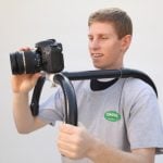
 With the blast of HDSLR comes the need to create a more comfortable way of shooting video with SLR shaped bodies. You can get one for about $2000 or make your own for about 7$.
All you would need for that is a IKEA cutting boards, a stove, and some pipes.
Yes, I did say IKEA cutting board.
Parts/Supplies
- 4 pc aluminum (or other) tubing with a matching diameter Drill bit. On my rig, the short rails are 8 1/2″ and the long rails are 22 1/2″ but you can adjust this to best fit your application.
- 1 Ikea Boholmen plastic cutting board or similar
- A small piece of foam for the shoulder pad, if desired.
- Several small screws or nuts and bolts with drill bit (and tap if desired) to match
- 2 bicycle hand grips
- The parts scheme as a downloadable PDF or png file
Here’s a short step by step of what I did to make the camera mount:
The Parts and The Metric System
First, yoiu will need to create the parts out of the IKEA cutting board. The scheatic PDF here has all the relevant drawings. Print it and paste it onto the board.
The initial rig was intended to be metric and use the standard 15mm x 60mm rod configuration, sadly 15mm supplies may not be easy to find. The PDF still has metric rods for compatibility, however, if you fail to find the necesary rods, you cna change them all to 5/8″. Actually, the move shows my work with 5/8″ tubes as I failed to find 15mm tubes.
And of course, if you like any size other than 15mm X 60mm, feel free to adjust and build upon the general idea.

The Frame
The first part to be cut are the two long pieces for the 4-hole frames. (Actually my first go was a 3 hole frame, but this did not set the camera far enough over to the left to line up the Z-finder with my eye. In the video you can see me working on the three hole version in places…)

With the long pieces cut out, (make sure to make them wide enough that there is a good amount of plastic remaining around the holes) find the center line of each of the two frame pieces and mark the center points of the 4 holes as accurately as possible. These two frames must line up exactly so that the tubes fit and stay nice and parallel.
I marked my center points with a calipers and a small drill bit. Then I drilled a tiny hole at each center point to guide the larger drill bit.
If you do not have a calipers, you can drill the two frame pieces at the same time stacked one on top of the other. You could even make them longer than needed and screw them together so that you know the holes are dead-on accurate. Then when the holes are drilled you could unscrew the pieces and trim away the screw holes.See the image below for more details

Cut out all the remaining frame pieces with a small band-saw. Chances are you’ll be left with really rough edges. Lightly sand each piece so that everything would have a clean and smooth professional look.

Once I you have the 2 4-hole frame pieces completed you can assemble the short rods and longer rods together in the frame to test the alignment.
The holes I drilled with my 5/8″ paddle bit were an exact match to the 5/8″ tubing which made the frame fit very snugly without any screws. (The image below has the plate and shoulder pieces on, but if should give you a good idea on how the rods and frame interact.

The Mounting Plate
Once you verify the the alignment, move on to the mounting plate.
Actually, the plate is just a small rectangle piece of the cutting board that you should screw to the 2 shorter rods. You can do this with 4 small screws.
Each of the 4 holes is countersunk so that the screw heads are flush with the surface of the plastic mounting plate.
You can tap the holes in the tubing as well so that the screws would thread into the rods. If you use a large enough screw you *may* be able to skip the threading process, or you could drill all the way through the tubes and put a washer and nut on the underside. (However, taping provided the cleaner and more professional look, so I did the extra work of threading the holes)
With the mounting plate securely in place, use a piece of paper and a pencil to trace the hole pattern from the bottom of your camera and transfer that to the mounting plate.
Next drill two 1/4″ holes in the plate. There is some logic to the place of making those holes on the plate.
You want to make sure that when your camera is screwed to the rig that you can still access the battery through the space between 2 rods. Take the time to make careful measurements so the holes on the plastic piece do not align the battery door in a position where you could not remove the battery.
As for making two holes here is my observation: I also noticed that if I only mounted the camera with 1 screw in the center hole that it could rotate a little bit even when the screw was tightened as tight as possible. Since my Zacuto base-plate has 4 mounting screw holes, I added a second mounting screw to keep the camera nice and straight. If you only have the center hole, a small piece of black rubber or fun foam glued to the top of the mounting plate might be enough to get a secure grip and prevent any rotation.
The Shoulder Piece
Next you should tackle the shoulder piece.
I wanted something that mounted to the rods via two holes like the rest of the frame, so I came up with the s-shape idea which ended up working really well.
Cut out the 14″ long piece of plastic and drill two holes with a 60mm spacing at one end.
Then bent this piece into the final shape by heating it very slowly over a gas stove. You have to do this VERY slowly or else you will melt or burn the plastic. It took a few minutes of slow heating, but by heating a little, then bending a little, then heating a little more, and bending a little more etc. you will eventually got the desired S shape.
When you have the right bend, ran the plastic under the faucet to cool it down and set the curve. This mate take some time and fiddling to get right. One of the perks of making the curve right, is since the shoulder piece is mounted without any screws, it is adjustable.

This is optional, to wrap this up, cut a piece of foam to the S part of the curve using spray glue. If you have never worked with thick foam before, this may be a bit tricky. You can saw it. Yes, saw.
The Handles
To make the handles cut out the two small hockey stick shaped pieces in the diagram.
Those pieces have two 60mm apart 15mm holes so that they would fit over the outer two rods on each side of the mount. The handles are just wide enough so that the bicycle grips would fit on them very snugly. If this is too snugly for your grips, sand the hockey sticks a bit.


Wrap Up
Of course, the process aboce is can be considered as a framework to be enhanced and improved. Below are my ideas and mods, would lvoe to hear yours.
- I added a few more 2-hole black frame pieces to cover the ends of the rods in the front and back of the two 4-hole frame pieces. I do not think these are necessary, but I did think they added a little finishing touch, and probably help strengthen the rig.
- Since finishing the original build, and the video, I have added a small aluminum strip along the bottom with two 1/4-20 threaded holes for accessories and a tripod plate.
- I also found out about a mod people are doing to add a cable release to their rigs for triggering the video button so I added one of those as well. You can see these in the pictures.
- I would like to add some weight to the back in the future as well to help counter-balance the weight of the camera, but I have not decided on what to use for that yet.
About the Author
Cris is a videographer editor based in Dallas Tx. To see more of his excellent work check his flickr stream.

Udi Tirosh
Udi Tirosh is an entrepreneur, photography inventor, journalist, educator, and writer based in Israel. With over 25 years of experience in the photo-video industry, Udi has built and sold several photography-related brands. Udi has a double degree in mass media communications and computer science.


Join the Discussion
DIYP Comment Policy
Be nice, be on-topic, no personal information or flames.