


The Complete Guide To Bulding a DIY Open Air Wireless Internet-enabled “Photo Booth” (with Slide Show)
Apr 25, 2014
Guest Author
We love it when our readers get in touch with us to share their stories. This article was contributed to DIYP by a member of our community. If you would like to contribute an article, please contact us here.
Share:
Over the years we’ve seen our share of photo booths here at DIYP. However, this guide from Mike Mikkelson (who also runs a photobooth business) is probably the most ever comprehensive guide I’ve seen to date. Aside from covering everything (EVERYTHING) from construction, software, printing and props, the fact that Mike runs is as a business makes it a field tested build. Enjoy!

I had been thinking of building a Photo Booth for a couple of years, but never seemed to get around to it. A good friend is getting married at the end of the year, and I’m am the Official Photographer for the event. In speaking with him about the wedding, he had assigned another friend of ours to create a photo booth. I had mentioned that I could help on that project as I had already done heaps of research on the subject. In chatting with our mutual friend, he was having issues coming up with reasonable solutions, and I brought up additional concerns and options.
- Did the Bride and Groom want an actual booth, as this might limit the number of people who could participate?
- Would an “Open Air Booth” be acceptable, this allowing groups of people to participate?
- Would they want the booth to product prints for the guests, and potentially themselves?
It was decided that a laptop running photo booth software and capturing images from a webcam would just not be good enough for this event. I said that I would take the lead on this and come up with a plan. Here are my personal requirements:
- Must be able to utilize dSRL Canon camera to capture great shots within the booth
- A Booth that is portable, and can be modified to use as a booth and open with a backdrop.
- Built-in Softbox for proper lighting
- Must be self-sufficient and users can figure it out themselves. Not sure if we’ll have an attendant at this event. (Remember, I’m the Official Photog, and can’t consume my time with the booth)
- Booth PC would be internet enabled and wireless
- Images would be automagically uploaded to the internet as backup as they were taken.
- Can be used as either a Photobooth or a Video Booth.
The construction
My DIY Photo Booth always included a built in softbox surrounding the camera and the LCD screen when I envisioned it in my head. I drew some sketches on my iPad and ventured to Home Depot to scout out supplies. Please keep in mind that I always intended to use as many supplies that I already owned. This included the base, which is a rolling work bench on casters that will hold my PC. I also already had multiple LCD screens that I wanted to mount to the booth. The PC was an old HP desktop that was destined for the dump, but powerful enough to run the photobooth software, so it got new life.
I began with a metal paint bucket and a florescent light cover as my base. What I discovered about the light cover is that the Acrylic was too brittle, and would probably have to abandon that idea. I pictured the LCD screen below the camera portal, or bucket, with a white, translucent material surrounding it to provide a lighting source.

I already had a couple of old 19″ LCD screens in the basement, as I had upgrade my monitors on my home PC to widescreens. These Dell screens would work great for the booth. I knew that I was going to use dSLR Remote Pro as the software, in addition to BreezeViewer as a slide show. Using this combination allowed the Photo Booth to run off one monitor and the captured images to display on the second monitor. I planned on attaching the 2nd monitor to the outside of the booth enclosure so people could see their own images after they finished their session.
I purchased a couple of Adjustable Tilting Wall Mount Brackets for LCD from Amazon, as this would make my build easier as far as mounting the LCD screens.

I cut a 1×6″ board to the height of my booth enclosure and positioned the bucket a the approximate level I was going to use. I also painted the inside a flat black using primer and then black paint. Using a second board, I attached the LCD mount. Now the LCD Monitor and the front lip of the paint bucket would be at about the same level.

I attached the bucket into its final spot, and drilled pilot holes and used 8 machine screws to hold it in place.

For the lens to fit into the bucket, I used a 4″ hole saw to cut the opening through the bucket and wood all at once.

I routed the back edge of the hole opening to be rounded. I plan on covering the inside of the enclosure with mylar to use as a reflective material to optimize the softbox.

Using a extra mylar emergengy blanket that I purchased for use with my DIY Octo Softbox project, I covered the boards and reattached the bucket and LCD mount.

To get a feel for how the monitor would look, I attached it to the board and balanced it on the cabinet to see it.

Next is building the enclosure. I knew that in order for this Booth to work for me, it had to be somewhat portable. I decided that I would use an existing tool cabinet for the base, and build the booth enclosure to fit on top of that rolling cabinet. I chose 2×2 boards, and created a frame.

Here you can see the back , which has a board to hold the 2nd LCD monitor, as well as the mylar covered board for the camera portal and main LCD, are fitted into the new frame.

The back side of the enclosure with LCD mount.

Testing the 2nd monitor. The LCD monitor on the front side is recessed into the frame, and is flush with the front edge of the portal opening. I wasn’t concerned about the rear side, and although does get mounted inside the main frame, does stick out farther due to the mount.

Patching some holes and filling in screw heads.

Here is the side panel, which will be removable to gain access to the inside of the enclosure.

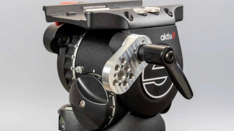
Adding the camera shelf. I will be using a manfrotto ball head to hold the camera and attached to this shelf.

The back panel of the inside of the frame, I’m using contact cement which will give a tacky surface to cover with additional mylar reflective material.

Emergency Blanket, which is already been pasted to the back wall of the enclosure.

Just need to trim the edges and let it dry.

After standing it back up, here is the enclosure with the sides and back panels attached.

I knew that I wanted the enclosure to light up, and not just use strobes, so I added a couple of light bulb sockets and wired them to a switch inside the enclosure.

Here is a shot of the enclosure with the 2 lights on. I know at this point I’ll have to add a couple of more lights to the top.

For the front panel, I gave up on the idea of using acrylic, and settled on using white fabric. I went to JoAnne’s fabrix to pick out some nice white silk material from the closeout section. Getting the fabric on sale makes my wife more happy than me, but it seemed to work out great. I dusted off my sewing skills and sewed some re-enforcement loops into the fabric. The idea was going to be to cut a hole in the fabric wear the portal needed to go through, but to ensure that there was still strength in the sheet to not tear when stretching it over the remainder of the box.

Ended up going with sewing 2 loops before cutting.

Cut the opening.

Test the can to ensure that it fits. It’s really tight, and will work fine.

How it looks with the fabric attached from the front.

Reattached the bucket with the fabric installed back to the original upright brace.

I built the frame so that it would have an additional frame inside the outside frame to act as a mount for the fabric. I stretched the fabric around the inner frame and stapled the silk to the 2×2.

Once the fabric was stretched and stapled to the frame, I needed to cut holes for the LCD mount to go through. I pulled out the trusty Duct tape and attached a piece to each side of the fabric. I used this technique to prevent the fabric from ripping once I cut through, as it was under some strain from pulling it tight over the frame.

He it is with the LCD Monitor attached. You can see that the fabric goes all the way around the camera portal and the LCD monitor.

Another shot with the lights on the inside turned on. With this much done, I knew that I definitely needed more lights on the inside.

Here is the enclosure with the additional 2 light bulbs mounted, and the softbox is much brighter.

Welcome screen testing on for the dSLR Remote Pro software.

I added another piece of 1×3 wood to the bottom to act as a mount for the arcade buttons, which will be configured to initiate keyboard strokes and mouse clicks to the photo booth software using the Teensy USB Development Board.


1/2″ pipe was used to create a bracket that was attached to the top of the photo booth to hold the 2 softboxes to either side of the booth. Pocket Wizard remotes and Canon 430 EXII flashes were used to add to the light of the built-in softbox. I used my vinyl cutter to create custom accents on the booth frame and behind the buttons. A white backdrop was placed in front of the booth, and tape was stuck to the floor in a box, to help users know where to stand. You can see in this next image where the boox was positioned in the corner of the reception call, and the slide show which is displayed on the back monitor. The projector is off during the father of the bride’s speech, but you can see how the softboxes are hanging off the pipe-bracket. The table next to the booth housed 2 Canon Selphy printers and the guestbook for guests to sign.

Software – dSLR Remote Pro
A friend requested that I come up with a solution for providing a photo booth for their upcoming wedding. I had created an Automate script for an old MacBook and Canon G9 as a cheap photobooth alternative a few years ago. However, I wanted to develop something a little more professional, and keep the cost cheaper than going out an renting a booth. My DIY Photo Booth project was born, and has been consuming my time for the past couple of months. One of the biggest challenges is deciding on which software to use for your booth, as there are many options available. I discovered dSLR Remote Pro by Breeze Systems, which is more than just a fully functional photo booth system, but also contains other features that can be used with my Canon dSLR cameras.
What I really liked about the photo booth features within dSLR Remote Pro was the ability to customize the interface to exactly what I needed. You can run the your system as a Photo Booth, or a Video Booth. You can customize and print photos, or just save them locally for use later. Since the DIY Booth was going to be used for a wedding, I wanted to be able to tailor the background images and user instructions for the event. I also wanted the interface to be user friendly and self-maintained. I installed arcade buttons to the enclosure that activated either photo mode, video mode, or start capture.
The computer that I used for this was an old HP dx2000 mini tower, running a Pentium 4, 2.80 Ghz processor with 2 GB of RAM. I was worried that this would be under-powered, as it was destined to be junked, and I saved it to recycle it in the booth. The phot obooth software by itself doesn’t take that many resources, but you add a slideshow running at the same time, plus a full print queue, this old PC worked hard. I definitely think that a modern multiprocessor PC with more memory would be wise, but I was able to get through both events without any computer freezes.
Here are examples of the Backgrounds I used for the wedding:

This is the background that is displayed when live view is not active. The black button simulates a CTRL-S to switch to Live View Mode.

This background shows the booth users a mirrored image of themselves in the box. Pressing the green button simulates a left-click.

Since the users tend to look at themselves in the LCD screen, I created this image to remind them to look at the camera. It is displayed 1 second before the camera clicks the shutter.


When the 4 images are captured, a processing screen is displayed before going back to the beginning of the sequence.
Button, Hardware & Teensy
The Teensy USB Development Board was used in my DIY Photo Booth Project to add arcade style buttons to the enclosure to enable the user to switch between Photo and Video Modes, Start the image/video capture, and enable/disable the camera’s live view. I originally had one button to activate Photo Mode, and a different button to activate Video mode. However, I found that dSLR Remote Pro had a simpler keyboard shortcut that could alternate between both photo and video modes. Here is my original sketch planning on how I would use Teensy.

The big Green button is LED backlit, and will be used to initiate either the Photo or Video countdown. Wiring was simple and straight forward. Power to the Teensy is provided by the USB Cable going to the PC. I found other teensy projects that were similar and used online documentation to figure out how to wire up the board properly. Some people used resistors and power from the teensy, but I kept it as simple as possible.

You can used compiled C programming code, or Arduino to configure the Teensy. I used Arduino, and here is my script that was uploaded to the Teensy. The final version had the big green button simulating a left click of the mouse, the black button to toggle live view (F6 button), and the yellow button to toggle back and forth between Photo and Video modes. (CTRL-S)
 /*
 Photobooth LED Buttons
 */
 // Setting variables that correspond to the PIN numbers that
 const int boothStart = 8; // Green Start Button - 8
 const int liveViewMode = 4; // Live View Mode Toggle - 6
 const int videoPhotoMode = 6; // Photo / Video Mode Toggle Button - 4
 int startButtonStatus = 0;
 int liveViewButtonStatus = 0;
 int cameraButtonStatus = 0;
 void setup() {
 pinMode(boothStart, INPUT);
 pinMode(liveViewMode, INPUT);
 pinMode(videoPhotoMode, INPUT);
 }
 void loop(){
 // Check Button Status
 startButtonStatus = digitalRead(boothStart);
 liveViewButtonStatus = digitalRead(liveViewMode);
 cameraButtonStatus = digitalRead(videoPhotoMode);
 // If boothStart button is pressed
 if (startButtonStatus == HIGH) {
 Mouse.set_buttons(1, 0, 0); // click left button
 // delay(100);
 Mouse.set_buttons(0, 0, 0); // release buttons
 delay(500);
 }
 // If liveViewButton button is pressed
 if (liveViewButtonStatus == HIGH) {
 Keyboard.set_key1(KEY_F6);
 Keyboard.send_now();
 Keyboard.set_modifier(0);
 Keyboard.set_key1(0);
 Keyboard.send_now();
 delay(500);
 }
 // If cameraMode button is pressed
 if (cameraButtonStatus == HIGH) {
 Keyboard.set_modifier(MODIFIERKEY_CTRL);
 Keyboard.set_key1(KEY_S);
 Keyboard.send_now();
 Keyboard.set_modifier(0);
 Keyboard.set_key1(0);
 Keyboard.send_now();
 delay(500);
 }
 }
Props – Make some yourself!

The wedding that the Photo Booth was built for, happened to land on New Year’s Eve. This virtually guaranteed that there would be hats, noise makers, and tiaras. I wanted to have some other props that could be brought out later in the event, and started looking around the house for options. I also went online to find some ideas, and discovered that there are many free resources for photo booth props. Popular opinion states that “Mustache on a Stick” is SOOOO 5 years ago, but I loved the idea. Due to the nature of this event, I didn’t want to spend tons of money on props, so making them is the next best, and cheapest alternative.

Inventory at latest Event:
- Mustaches on a stick
- Felt “Stick-on” Mustaches
- Goofy glasses
- Cheese Head
- Batman Mask On a Stick
- Pirate Bandana and Eye Patch On a Stick
- Cowboy Hat On a Stick
- Hawaiian Lei
- New Year’s Eve Party Hats and Glasses
- Bunny Ears on a Stick
You can make your own Photo Booth Props using a number of available Online resources. Here are a few links to get you started.
- Jordan’s Oh Happy Day – Photo Booth Props
- Photobooth Props Set #3
- Mustache on a stick tutorials
- And of course, you can just Google “Photobooth Props” and look at the image gallery for ideas.
Testing – Bad Holiday Sweater Party
In order to ensure that the Photo Booth was operational for the New Year’s Eve wedding, I arranged to test it out at a Bad Holiday Sweater party. This not only was valuable in creating a run through on transporting the booth, but setting up and configuring the lighting and photo booth software.
The party had a number of kids who were able to figure out the booth in only a few seconds, which was great news for the arcade buttons ease of use. It only took about 20 minutes from the car to get it fully set up inside. It was not only fun, but this preparation ensured that the wedding would go smoothly. The Breeze Systems software worked great, as I was able to create custom screens specifically for the Holiday get together.

This is the Screen that is enabled when “Live View” is off. I programmed the black arcade button to switch to this mode when the booth was not being used.

This is the background screen while the booth is idle, but in Live View mode. The 5D Mark II Canon camera displays the users in the booth in mirror mode, so it looks like a mirror.

There are a number of screens that are displayed in sequence before each picture is captured. I had the booth configured to take 4 images, so I made 4 different backgrounds.

Since it’s natural for users to watch themselves on the screen, I created a background to display 1 second before the images is captured to remind them to look up at camera.

After the 4 images are captured, this is the processing screen that displays to the users. The Breeze system software can be customized with optional screens, and allows the booth to be tailored specifically for the event.
Here are a few results:


The Wedding!

The New Year’s Eve Sugar Wedding at the Edgewater Hotel in Madison, Wisconsin was epic. The DIY Photo Booth was built specifically for this event, and it turned out fantastic. The booth was busy non-stop for almost 6 hours, and was described as the hit of the wedding.
Rules of the booth!

Aside from a few minor glitches in the beginning, the booth ran fairly smoothly for the duration. A few printing issues, and initial remote flash issues were cleared up, and people were enjoying the open-air booth the entire night.
Here is the booth and printer table at the reception. You can see here the mounted softboxes, as well as the GoPro HD Hero 2 on a flexible mount. The built-in softbox provided illumination to help with live view preview. You can also see the projector on the top of the booth pointed perpendicular to the user area showing the slideshow up on the screen. Images were added to the slideshow as they were captured using the Breeze viewer software. The screen on the back of the booth and the projector were mirrored to show the same slide show on both screens.
Here are some final images with the overlay:
Backdrop Casualty: Too much to drink? Why not attempt some crazy poses and fall into the backdrop! It was funny at the time.

The Bride and Groom: Hugh and Annie!

We learned that you need to ensure that you have someone monitoring the booth so people stand in the right spot. My wife was also kind enough to help people with the printed images and the guestbook. Apparently, 2-sided tape is pretty complicated, and some people just wanted you to do it for them. Also, people cannot seem to keep their hands off the printers, and couldn’t understand that the paper goes through a few times until it’s done. Having a guestbook table monitor was key.
I also learned that having enough time before the event to test lighting is essential. The mood in the room was different from when we set up the previous day, so we had a bit of a delay getting this configured at the start of the event. Considering that we used remote flashes with softboxes, it worked out great. Just ensure that the flashes, pocket wizards, and camera all had fresh batteries. I had to change the battery on the camera 2 times before the end of the 6 hours. Live view definitely takes a toll on the charge.
If I were to have a go at this business for other events, and not just a friends wedding, I’d want to ensure that I upgraded to a faster printer. Towards the end of the night, we were almost an hour behind in printing, as we were printing 2 copies of each overlay; one for the guestbook, and one for the users. We switched this to one copy after a majority of people had gone through the booth , to try and catch up.
The project was a neat addition last minute. Projecting the images up on the screen above the photo booth generated and kept interest in the booth all night long. Highly recommend using that again. The cloned second monitor had issues with VGA, and had a green tint. I think I’ll use the booth with the digital DVI cables in the future to prevent this.
The guestbook was also popular with the guests, and using the images from the photobooth gave them a unique and creative momento that was signed by everyone at the party.

Overall, I’m very please at the results, and the Bride and groom are happy. Everyone complimented us on a neat idea, as many people have not seen this before. The question is, do I continue to offer this as a service???
I also attached a GoPro camera to the booth to capture a time lapse of the users. It was a bit dark, but still fun to see how the night progressed:
Special thanks must be given to the following people, who ensured the success of the photo booth:
Katie Mikkelson for manning the guestbook station, and making sure guests didn’t touch the printers or run off with the prints.
Jaron Berman for helping set up and configure the lighting.
Matt Schroeder for grabbing my camera while I was operating the booth, and taking images at the reception.
About The Author
Mike Mikkelson is a photographer and a photobooth operator from Wisconsin. This post is based on Mike’s series on building a photobooth.

Guest Author
We love it when our readers get in touch with us to share their stories. This article was contributed to DIYP by a member of our community. If you would like to contribute an article, please contact us here.


Join the Discussion
DIYP Comment Policy
Be nice, be on-topic, no personal information or flames.
8 responses to “The Complete Guide To Bulding a DIY Open Air Wireless Internet-enabled “Photo Booth” (with Slide Show)”
you guys are getting specific.
Moyo Mitchell
Yep, this is happening
This guide is awesome. If Mike Mikkelson is reading the comments for this post, would you mind sharing the outside dimensions of the frame you constructed and the height of the toolbox you used?
The dimensions are 28″ wide x 19″ deep x 36″ tall. The rolling cabinet that I used is 37″ high on the casters. Hope this helps.
I don’t think this is something most of us would pursue. With that said, this is freakin’ awesome.
You mentioned Breeze Viewer software, but I don’t see it listed on the Breeze website. Do you know if it was discontinued?
Great idea and great execution. I have done many events with an open style photobooth and am eager to build a photobooth I can rent and walk away form.The only drawback seems to be lugging that tool chest to events. I thought of replacing the tool chest with a Matthews High Rolling Stand that can accommodate up to 88 lbs. Of course the stand would require a platform.