


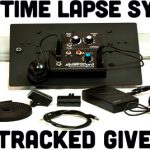
Slidetracked, A 3D Printed Time Lapse Dolly
Mar 5, 2012
Udi Tirosh
Udi Tirosh is an entrepreneur, photography inventor, journalist, educator, and writer based in Israel. With over 25 years of experience in the photo-video industry, Udi has built and sold several photography-related brands. Udi has a double degree in mass media communications and computer science.
Share:
Derek Mellott is no stranger to Timelapse sliders and dollies, he is a genius. In fact our most popular slider design on the blog is Derek’s design. Today, Derek explains how to DIY the Slidetracked, a fully featured, easily assembled, 3D printed DIY dolly. If you just want the features, but do not want to build one, you can get a pre-assembeled one from Indiegogo too.
Parts List
The following 3D parts (you can print your own, or get buy them here)

- 4x Slidetracked Slider Bracket
- 2x Slidetracked Belt Grip top
- 2x Slidetracked Belt Grip bottom
- 2x Slidetracked Microswitch Mount
Optional 3D parts.
- 2x Slidetracked Idler
- 1x Slidetracked Cable Clip x 6
Store bought parts:
- 14t Pulley that fits the belt and motor you use.
- 6.5′ timing belt, I’m using a 5mmHTD 9mm or 3/8 XL
- 1x 3″x 1.5″ x .188″ aluminum channel 6″
- 3x 1.5″ x 3/8″ x 2.5″ flat bar
- 1x 9″ x 9.5″ x 3/16″ aluminum sheet
- 1x 1-2 rpm motor
- 1x PWM
- 1x enclosure for the PWM
- 4x switched DC power jacks
- 4x DC barrel plugs
- 1x Normally open momentary switch
- 2x Long arm lever micro switches
- 1x 3/8″x 3/4″ x 6″ UHMW
- 1/4 20 screws 3/4, 1/2, 1 1/2, nuts, nylocks.
Build The Dolly
We need to layout the plate to mark all the holes. The first thing you want to do is find the center and distribute the the four Slidetracked Slider Brackets from there. The most important part is to make sure your brackets are straight there is room to move the brackets tighter and looser to the rail.

Mark the holes for the two Idlers, the placement of these will determine where you mount the Belt Grips on the rail, make sure you leave enough room from the edges of the rail so that the dolly will clear the Belt Grip bottom, be sure to read the rail step before drilling these holes.
Next mark out where you want your motor to go. I chose near the edge next to a Slider Bracket, This keeps the motor out of the way.
Pick where you want to put your camera, don’t get too close to the edge.
You will need to mark out and drill the holes for the Microswitch Mounts but wait until the rail is built so that you can line them up with the Belt Grips, this is what they bump into.
Now center punch your markings so that the drill bit won’t dance around and the holes go where you want them.
I used 5 different drill bits and a step bit. The holes for the Slider Brackets need a 1/4″ hole. The holes for the idlers are threaded 1/4 20 so the drill the holes with a 13/64 bit. The hole for the ball head is 13/32, the hole for the motor shaft is 1/2, and the holes for the Microswitch Mount and to mount the motor is 1/8. After the holes are drilled use a larger drill bit to chamfer the holes a little, just to clean it up a bit and remove burrs.

Cut four 1″ lengths of UHMW and push them into the four Slidetracked Slider Brackets.


Place the 3/4 1/4 20 screws in the (bracket* remove the s ) holes and mounts the brackets, put the nuts on but don’t tighten them up yet. once all four brackets are on put the dolly on the track and squeeze the brackets snug to the rail, don’t make it too tight but make sure there isn’t room for the dolly to twist.


The Rail
This is the single most expensive piece of the whole system, it is also the most important. You need to use something straight and strong, for this I used something that I think you can get in any decent sized city and easy to find online. I used 3″ x 1.5″ x .188″ aluminum channel.
There are 10 holes to drill in the rail 4 for the timing belt holders and 6 for the tripod risers.
Lets start with the risers.
The risers are needed so that the dolly does not hit the tripod head below. I used 1.5″ x .5″ flat bar aluminum 2.5″ long. I marked the center for the tripod hold and the other two holes for mounting to the rail.

Drill and tap the holes with (*13/64 forgot to add bit size)bit and 1/4 20 tap

Find the center of the bottom of the rail. I offset the riser 2.5″ from the edge of the rail. mark the outer two holes from the riser and drill with a 1/4″ bit. do the same on the other side and the center of the rail to give you 3 tripod points.

Now its time to mount the Belt Grips, the placement of these is very important. you have to line them up with the idlers underneath the dolly so that the belt is straight. once you figure out the location simply mark the holes and drill them with a 13/64 drill bit and cut the threads with a 1/4 20 tap.
Screw all the pieces on and your rail is done
The Electronics
Now it’s time to wire up your PWM. The basic use of the PWM is very simple connect battery to PWM, connect PWM to motor, easy. We want to complicate things a little. The kill switches are a safety feature, they will stop the unattended dolly at the end of it’s run. It is fairly simple to wire up but I find it hard to explain, here we go.
The idea here is to have the micro switch interrupt the positive to the motor. this is done running the positive through the normally close connection on the switches, when the switch is triggered the power gets cut. I’ve added a bypass so that you can back the dolly away from the trigger point. this is just a normally open switch that is on a line the goes from the battery to the motor, when pressed the power will by-pass the micro switches.
Laying out the enclosure takes a little time to make everything fit, take your time. Attach the enclosure to the dolly with some two sided foam tape, or you can drill holes if you want. (click the circuit to enlarge)


There you have it. Of course, if you have more money than time you can get one by backing the project at indieGOGO.

Udi Tirosh
Udi Tirosh is an entrepreneur, photography inventor, journalist, educator, and writer based in Israel. With over 25 years of experience in the photo-video industry, Udi has built and sold several photography-related brands. Udi has a double degree in mass media communications and computer science.


Join the Discussion
DIYP Comment Policy
Be nice, be on-topic, no personal information or flames.