
















How to build your own laser-powered DIY shutter speed tester
Jun 4, 2024
Don Goodman-Wilson

John Aldred is a photographer with over 25 years of experience in the portrait and commercial worlds. He is based in Scotland and has been an early adopter – and occasional beta tester – of almost every digital imaging technology in that time. As well as his creative visual work, John uses 3D printing, electronics and programming to create his own photography and filmmaking tools and consults for a number of brands across the industry.
Share:

My collection of analog cameras is in a state. Specifically, in the state of “I have no idea whether the shutter speeds on these things are the least bit reliable”. I also don’t have a ton of money to throw at just getting everything CLA’d. And sometimes getting a CLA isn’t a guarantee that the shutter is actually working as expected…ugh.
So what is an ex-electrical engineer to do? Build their own shutter speed tester. Follow along, and learn how to shoot lasers at your cameras for fun.
Theory
The idea is that we can shoot a laser through the shutter at a high-speed laser detector. Then we can time how long the detector is activated to calculate the shutter speed. Laser detectors are much faster than other kinds of light detectors, and we’ll need that speed to accurately measure shutter speeds of 1/1000 or faster. we’ll also need a small computer to measure the speed, and calculate and display the results.
Shopping List
Here’s what we need to get started.
- Arduino Uno. This is a basic, inexpensive microcomputer to coordinate everything. There are thousands of cheap clones on the market that are just as good as the original: You don’t have to get the brand name.
- Arduino Prototyping Shield (or small breadboard). This is a small expansion board for the Arduino that breaks out a few connectors that we need. You can also use a small breadboad if you like. Again, you can get the cheapest one. Just make sure it comes assembled if you’re not up for soldering.
- Jumper wires. These are the wires to connect all the things together. You’ll need a handful of male-to-male and male-to-female. Try to get longer ones, at least 20cm, ideally more.
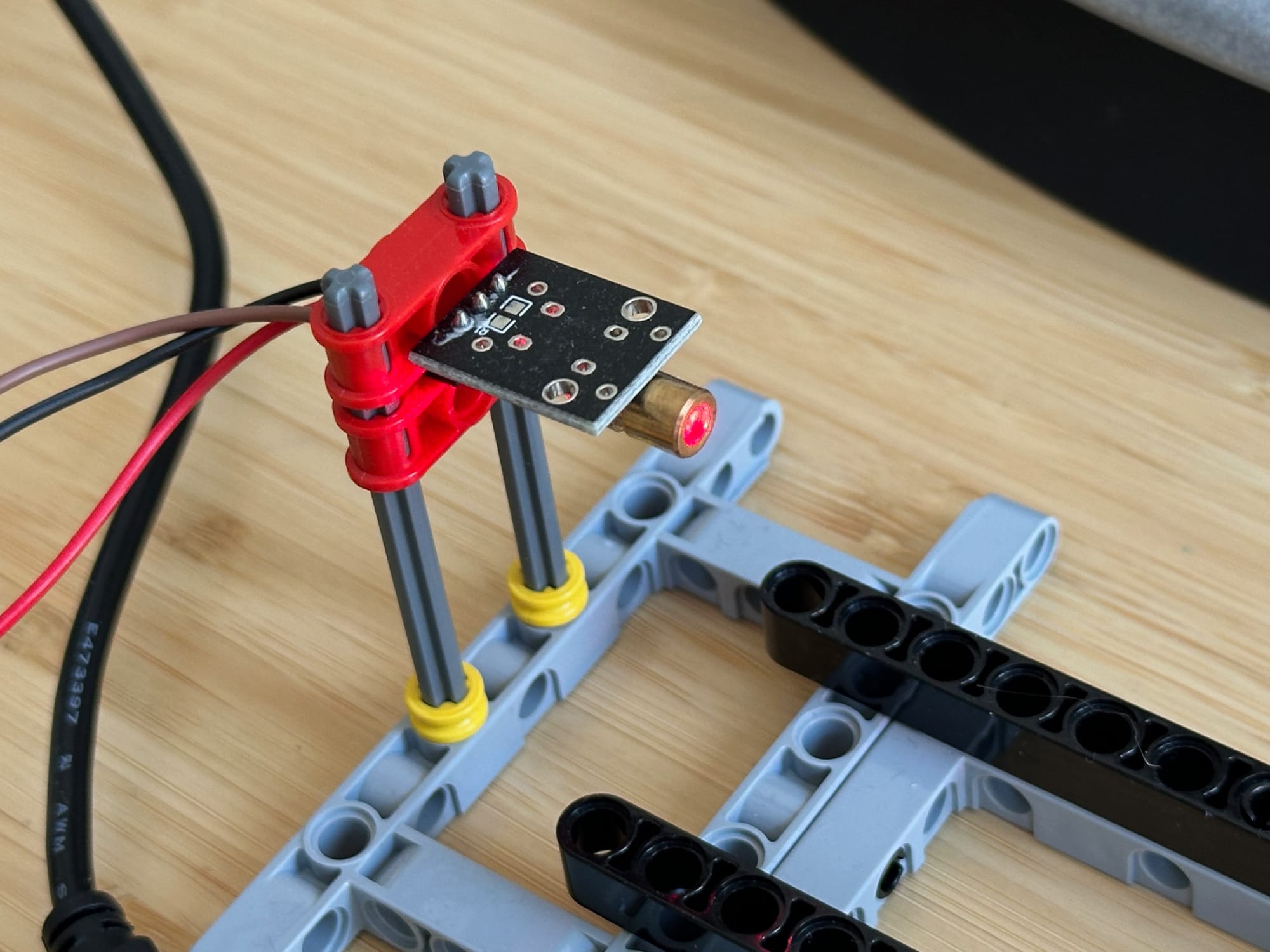
- KY-008 Laser Transmitter module. This is our laser beam!
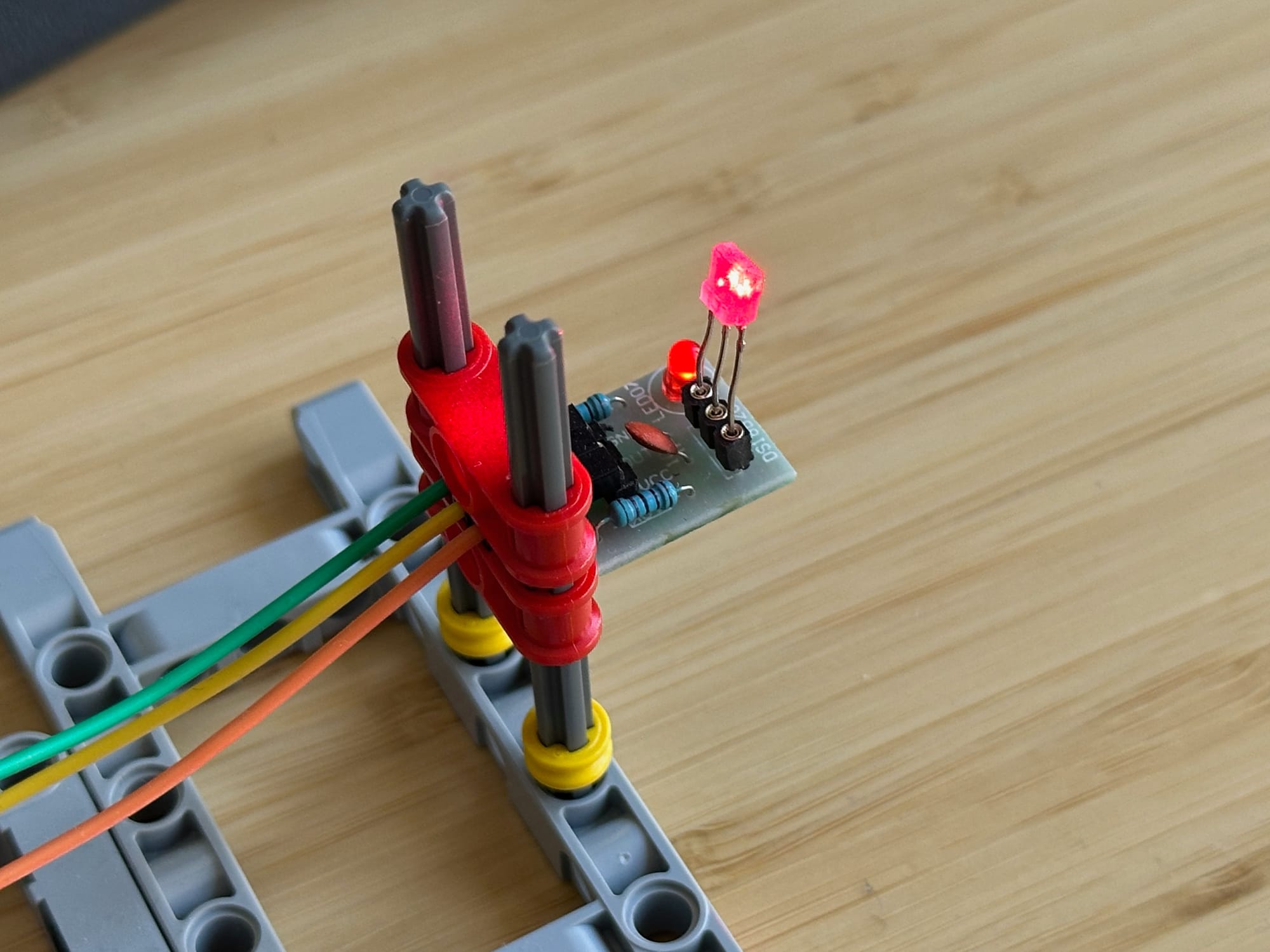
- ISO203 Laser Receiver module. This will detect our laser beam. Both of the laser modules are available cheaply from China.
- Something to hold it all together. Maybe you own a 3D printer and can whip something up? Or maybe you’re basic like me, and only have some Lego lying around. Whatever it is, you need to find a way to hold the Laser Transmitter so it points at the Laser Receiver, and has room to place your camera between them.
Wire it Up
First, let’s wire all the bits together.
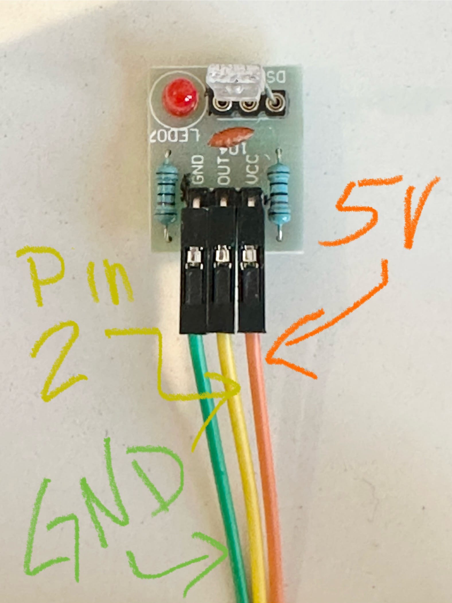
- If your Laser Receiver came unassembled, this guide will set you right.
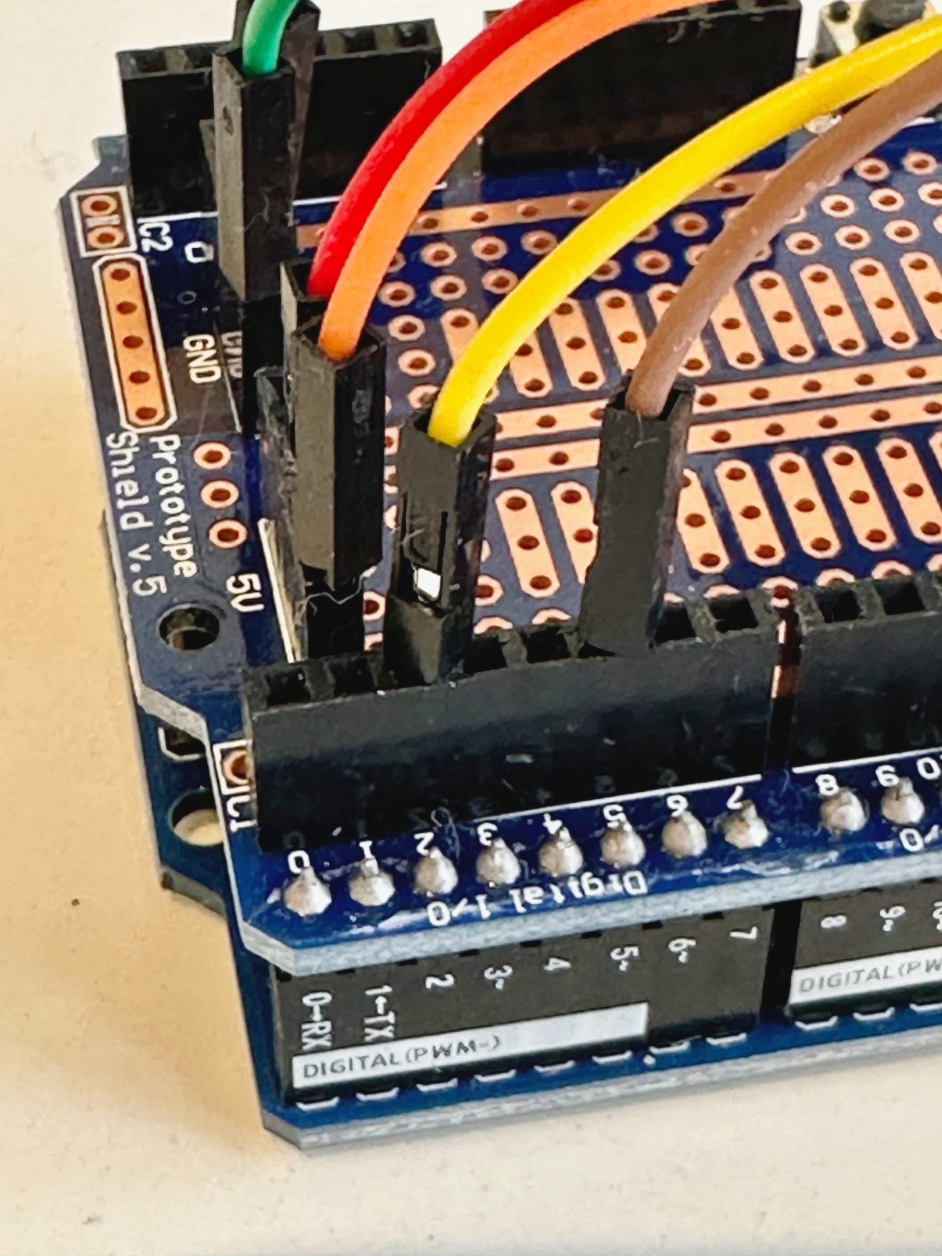
- If you’re using a Proto Shield, stack it on top of your Arduino, like in the image above.
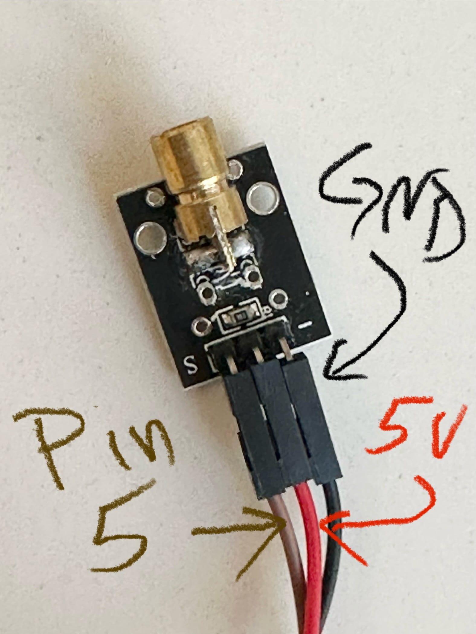
You’ll need six male-to-female jumper cables, three for each module. Each module needs a connection to power (5V), ground (GND) and one of the signal lines (Pin2 and Pin5). A bare Arduino only has one place for the 5V line, which is why I am using a Proto Shield, which breaks it out into several outputs.
You can also use a small breadboard to break out the 5V line into more than one. (Note that the colors don’t actually matter, but it helps to keep things straight!)
Assemble the Rig
Next, let’s build a rig to hold everything together. Unfortunately this part is up to you. But here’s a photo illustrating how I did it with some Lego Technic pieces I had lying around:
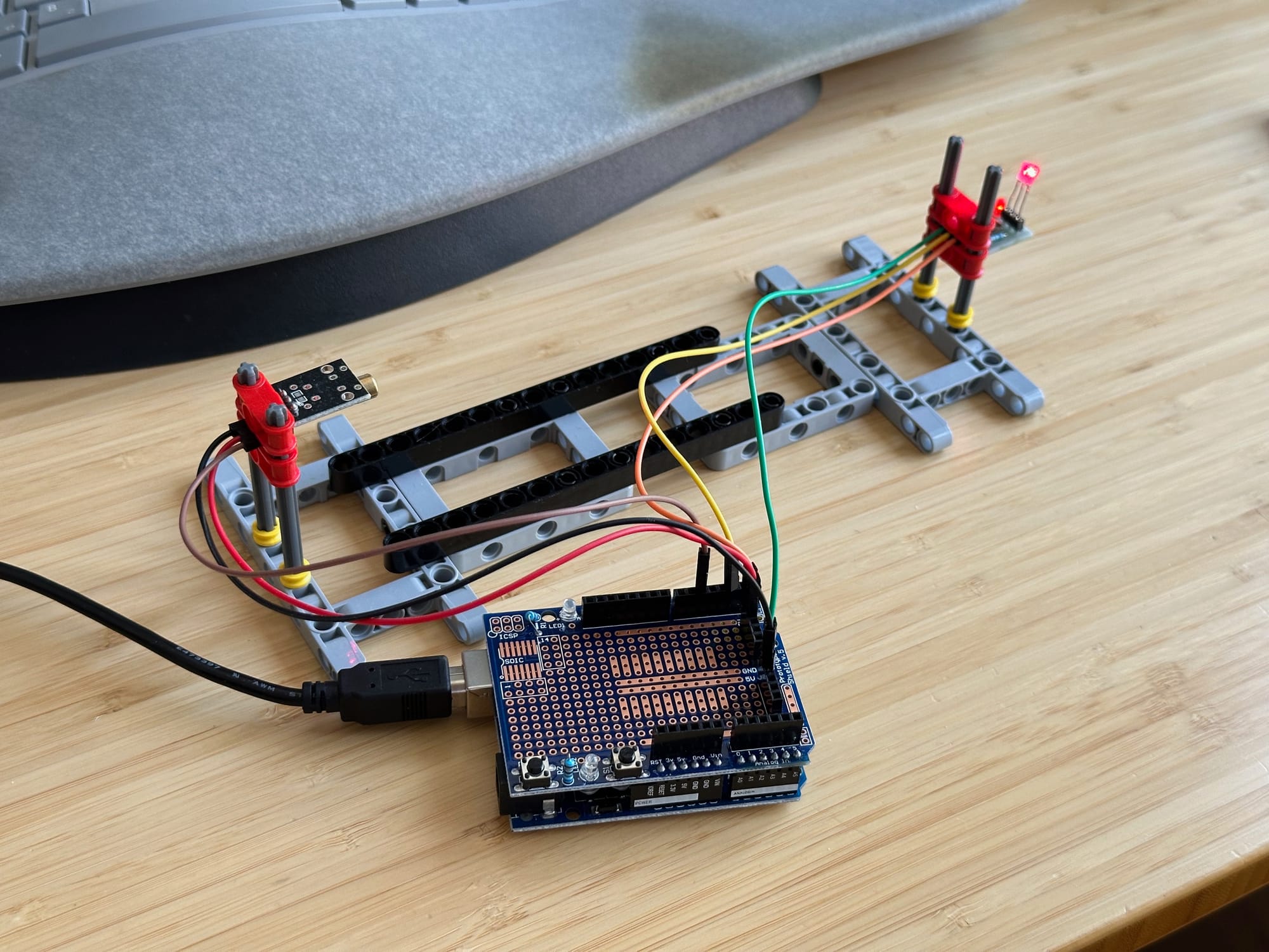
Notice that the Laser modules are raised up a bit, and can be adjusted vertically. Notice the rather large gap between them—this is so I can fit my Mamiya RB67 lenses between them! If you’re only testing 35mm camera bodies, you don’t have to go this big.
Upload and Run the Software
You will need to download and install the Arduino IDE (Integrated Development Environment). This software tool let’s you create new software for your Arduino (which they call a “sketch”), upload sketches to the Arduino, and monitor the text output from the run.
Once installed, plug in your Arduino, create a new sketch in the Arduino IDE, and copy-paste the code below into editor. Then hit the play button in the Arduino IDE to upload the sketch and set it running.
// pins for KY-008 Laser Diodes
#define LASER_DIODE_1_OUTPUT 5

// pins for ISO203 Laser Receivers
#define LASER_RECEIVER_1_INPUT 2


volatile uint32_t ts_1_start_us = 0;
volatile uint32_t ts_1_end_us = 0;
volatile bool speed_1_measured = false;
volatile bool curtain_1_measured = false;

// variables for calculated values
double shutter_speed_1_ms = 0.0;
double fractional_shutter_speed_1 = 0.0;


//---------------------------------------------------
// Detector 1 interrupt handler
//---------------------------------------------------
void detector1(void)
{
  if (digitalRead(LASER_RECEIVER_1_INPUT))
  {
    ts_1_end_us = micros();
    speed_1_measured = true;
    curtain_1_measured = true;
  }
  else
  {
    ts_1_start_us = micros();
    speed_1_measured = false;
    curtain_1_measured = false;
  }
}


void setup() {
  Serial.begin(115200);
  Serial.flush();

  pinMode(LASER_RECEIVER_1_INPUT, INPUT);
  pinMode(LASER_DIODE_1_OUTPUT, OUTPUT);

  attachInterrupt(digitalPinToInterrupt(LASER_RECEIVER_1_INPUT), detector1, CHANGE);

  digitalWrite(LASER_DIODE_1_OUTPUT, HIGH);

  Serial.print("Starting up");
}

void loop() {
  // put your main code here, to run repeatedly:
  if(speed_1_measured) {
    speed_1_measured = false;
    double shutter_speed_us = (double)(ts_1_end_us - ts_1_start_us);
    shutter_speed_1_ms = shutter_speed_us / 1000.0;
    fractional_shutter_speed_1 = 1000000.0 / shutter_speed_us;
    // Serial.print("t1_s=");
    // Serial.print(ts_1_start_us);
    // Serial.print("us   t1_e=");
    // Serial.print(ts_1_end_us);
    // Serial.println("us");
    Serial.print("Speed 1 = ");
    Serial.print(shutter_speed_1_ms, 1);
    Serial.println(" ms");
    Serial.print("Fractional Speed 1 = 1/");
    Serial.println(fractional_shutter_speed_1, 1);
  }
}
Running a Test
Make sure the laser beam is hitting the receiver. The place your camera with the back open in your testing apparatus. Make sure the laser is hitting the shutter, roughly in the center. Then fire off a test shot!

The output from the sketch will arrive in the Arduino IDE in the “serial monitor”, which is a window showing text sent back by the Arduino. If you’ve set your shutter speed to 1/500, for example, in the serial monitor, you should see something like this:
Speed 1 = 2.0ms
Fractional Speed 1 = 1/500
Of course, your shutter speed won’t be spot on…so maybe it will be more like this:
Speed 1 = 1.85ms
Fractional Speed 1 = 1/540,54
How Bad Is It?
I am a sucker for a good spreadsheet. So I made one to capture my test results. I recorded three samples per shutter speed setting, and then set the times in milliseconds into a spreadsheet I made to analyze the results.
You can download the template I made for yourself!
The spreadsheet averages the three samples, then calculates both the difference between the actually measured speed and the nominal speed in stops, as well as the sample variation. It then charts out the results, and calls out abnormal values.

As you can see, I need to contact my shop that repaired my Canon P—it’s already fallen out of calibration. At the top end, the shutter is much, much too slow—a stop and a half at 1/1000!—and the variability in shutter speeds is slightly too high at 1/1000.
Troubleshooting Your Shutter Speed Tester
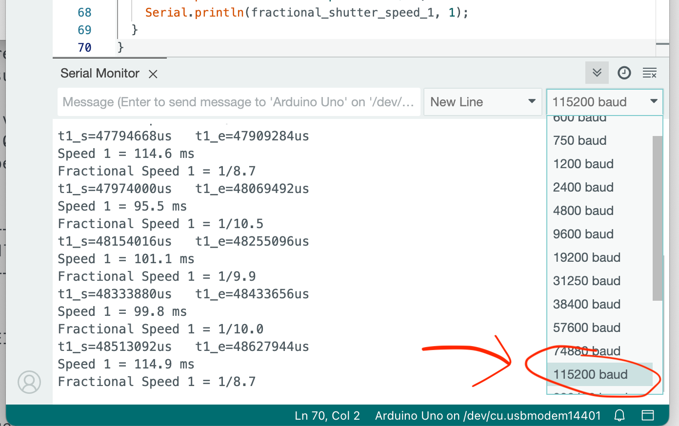
If you aren’t seeing any output on the Serial Monitor in the Arduino IDE, the serial port might be misconfigured. Make sure the port speed is set to 115200, as in this screenshot:
Source Code and Credits
This project is adapted and simplified from Stuart Brown’s excellent (and much more comprehensive) shutter testing project. If you want to go deeper with this, and maybe build something more sophisticated, his project has got the good stuff. Thank you Stuart!
See more from DIYPhotography.net on Google
Add DIYPhotography.net as a trusted source. This makes
our stories more likely to appear in your Google Search results.
 Add as a preferred source on Google

About Don Goodman-Wilson
We love it when our readers get in touch with us to share their stories. This article was contributed to DIYP by a member of our community. If you would like to contribute an article, please contact us here.



Join the Discussion
DIYP Comment Policy
Be nice, be on-topic, no personal information or flames.
6 responses to “How to build your own laser-powered DIY shutter speed tester”
John Nevill this is for film cameras, not digital.
Glad Nicolae Părău film? who can afford film these days? Lasers and film – are these people rich? 🤣🤣🤣
John Nevill damn you are thick. You didn’t even bother to look at the picture, nevermind the article, but bothered to write a dumb response.
Glad Nicolae Părău It’s called humour, it probably doesn’t translate into your native tongue.
Someone has too much time on their hands. But at least this is actual DIY. The first I’ve seen form you guys in a long time. Usually its reviews of products or some article about AI which isn’t even photography.
Nice project. Are you sure this type of tester is accurate with shutters other than leaf? I read somewhere that for focal plane shutters such as in Canon P both shutter curtains have to be measured, at least at speeds shorter than 1/500th of a sec. to give reliable readings. Anyway, congrats on the project and thanks for sharing.