Build An Amazing Super Versatile DIY Time Lapse Dolly
I was literally screaming with joy when Derek Mellott (you know Derek, he likes Barbeque and time lapse movies) showed me his latest Time Lapse Slider Dolly. Then, I literally fell from my chair when he suggested to share the build with DIYP readers.
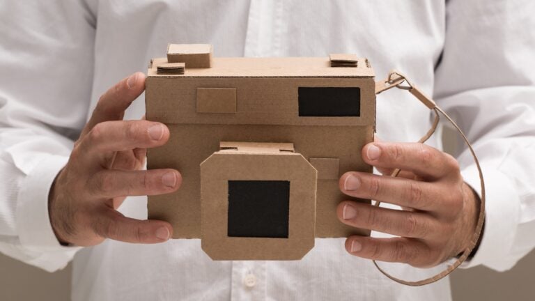
Now, every once in a while we have a "dare" tutorial, one that will kill an entire month of weekends (and then some). Those are not for the faint of heart, but the results and satisfaction from completing one of those projects in unbelievable. (see the battlefield pinhole camera for example). It is the same with this project - it is not an easy task, it takes woodmenship, electronics know-how, and plenty of time, but the results are stunning.
(But hey, you know what, even if you just pick up one of the ideas in this post, it would rock. For example, building the collapsible rails idea to be used with the cheapo motor slider puller)
The movie comes first - this should get you motivated - then the instructions. Embrace yourselves.
This is how I built my time lapse dolly, it was made with a whole bunch of trial and error, hopefully this will help you build yours.
A lot of the stuff I used I had on hand, don't know where I got it, or have no idea what it worth but I'll do my best at giving you a complete list of what I used and where you might get it.
This is very much a "prototype" build and posses very little polish, I would approach this post as a very rough guide of what you should do, do not be afraid to substitute the parts I used for parts that you have or can get easily
Building The Rails
I will start with the rails because I found it super simple to set the width of the dolly cart if you already have the rail made.
Parts and Tools
(all costs are an estimate, I didn't pay close attention to costs because it scares me)
- 2 x 8ft 1" square aluminum tubing $30 each here in Canada probably much cheaper down south.
- 1 x 4ft 1/4 20 threaded rod $2
- 6 x 1/4 20 hex bolts...yeah (aka barrel nuts or Chicago bolts) $1 each.
- 6 x 1" steel hinges $2-3 a pair.
- Drill bits and a drill and a 1/4 20 tap/ thread cutter, preferably a drill press to keep things straight.
- Something to cut the aluminum tubing, I used my compound miter saw.
- Hack saw
- Allen wrenches
Step 1 - Cut the rails to length
I originally used the full 8ft but found it a pain to move around and handle in general so I cut mine down to six feet leaving me with two 2ft pieces to use for other parts.
Step 2 - Cut the cross members.
The overall width of my rails is 6.5 inches so my cross members are 4.5 inches long and I used 3 of them. You can make these any size you want, remember the width of your rails determines the size of your cart.
This is also a good time to drill the holes where you will attach the tripods. Measure out the center of the cross pieces and drill a hole, I used a no. 2 drill bit then ran the 1/4 20 thread cutter bit into the hole. This will be the bottom of your cross members. test this on a piece of scrap first.
Step 3 - Attach the cross members to the rails with the hinges.
I clamped it all together and then put the hinges in place to mark where to drill the holes.
This is very important to get right so take your time and make sure everything is square and the hinges are flush and your holes are marked out correctly. After you have marked the holes for the hinges go ahead and drill your holes.

You are going to want to drill the right size hole for the screws that came with the hinges. test it out on a scrap piece of aluminum, if the hole is too big the screws won't bite enough to hold it all together and the hole is too small you will strip the screw head or break the screw trying to get it in.
Step 4 - drill the holes for the "clamp bolts"
These bolts are what make the rails rigid. You have to drill a hole big enough for the shaft of the barrel nuts to fit in. Mark the center of your cross members and transfer that mark to the side of the rails.


Do not drill your hole for the barrel nut in the middle of the rail!
Make the hole as low as you can without the lip of the barrel nut going below the bottom of the rail, you need the top of the rail to be clear for the bearing to roll on. See image.

Now you cut a length of the 1/4 20 threaded rod that will reach in between the two barrel nuts. You may have to trim it down or cut a new piece if it's too short, no worries this stuff is cheap. Make sure you get a good fit and you can tighten good, you don't have to tighten too much but you don't want any movement in the rail. You want to do this for all three cross members.
There you go! You now have a fold able rail!


Adding a Pulling System
This is the part that you will need to figure out for yourself. I will show you what I did but the parts I used I don't know what they are or where they came from.
The good news is that there are cheap parts made for this purpose but I wasn't going to spend $20 to ship a $3 chunk of plastic to Canada.
Parts
- 1" square aluminum tubing. I used the bits cut off of the rails when I shortened them.
- 1 1/2 inch 1/4 20 bolts x 4 $.50 each
- Timing belt clamps. I used some mystery things but you can get real one here. Just make sure you get the right one for your belt.
- Timing belt. I used a HTD 5m 9mm belt. It cost me about $15 You can get one here. (Or on amazon)

As you can see from the pictures I used the chunks of aluminum to attach the clamp to the rail.


The trick here is to make sure the belt is level with the pulley on your cart, That above all will determine how you mount your clamp, this is just how I did mine.
You will also notice that there are a bunch of bolts occupying a small space, keep this in mind when you are making your holes.
This step is simple. Attach clamp to chunk of aluminum, attach that to the rail, DONE! just make sure it is level with the pulley.

Pick Up Truck For Your Camera
The title of this step is accurate, you need to build this like a truck, it starts with a frame, you put on some wheels and a motor, add some electronics then load up your gear.
I didn't take pictures while I build this because this is the part that evolved the most of the six months I spent building this set up. I will do my best to walk you through it. If you are unclear about anything please ask in the comments and I will tell you everything I know.

Parts
- 3/8 threaded rod $3-4 bucks for 3-4 feet
- 3/8 lock nuts
- 3/8 nuts
- 3/4 aluminum angle $10? for 4 feet
- 10x30x9 Bearings $1 each you will need 10 of them. I have no idea what those numbers mean, it is what was on the box.
- 3/8x1/2 x1 bronze bearings $4 for the pair of them. These are oil impregnated sleeve bearings that the belt slides past by the pulley
- Pulley $17 I used one of these.
- 1 1/2 inch 1/4 20 bolts I used a bunch, buy a bunch, they are handy
- Wire rope clamp - I used 4 of these, I'm not sure what size I used just make sure that the 3/8 threaded rod fits nicely in it.
- Washers that fit the 1/4 20 bolts, you can never have too many
- 1/4 20 nuts
- 1/4 20 lock nuts
- Shoulder bolts? I lucked out and found these bolts at home depot and the sleeve bearings fit perfectly on them there is a picture below.
- 1/4 plastic pluming pipe, the whitish flexible stuff used on sinks? 12" is more than enough
- Motor $50-60 PLUS SHIPPING. I used a .45 rpm Dayton gear motor. * notice that it is (point).45 rpm not 45 rpm* I got it from Servocity.
- Ball head. I used a Benro BH00 it's cheap and works great, use whatever you want just make sure is has a quick release plate.
- Some sort of metal to use as a base, I used a steel electrical box cover, make sure whatever you use that it is big enough to mount everything on.
I will deal with the electronics on the next step.
I'm not going to go oven every little step in this build, there are too many, the pictures should help on what I leave out. However don't be afraid to ask questions.
Step 1 - Cut the 3/8 threaded rod to length
7.5 inches or so should do
Step 2 - Cut your 3/4 aluminum angle to length.
This can match the length of whatever you use as a base plate
Step 3 - Drill the holes for the 3/8 rod in the angle.
Now the placement of these holes is very important. I had mine centered but there was no way to make the motor to fit like that so I had to offset them. The measurement in between the rods was arbitrary, I just chose a stable looking width, you may want to put some more thought into it.

Make sure you make your holes in the exact same spot on both pieces of angle, this must be straight so it can be square.
Step 4 - Add The Bearings
It doesn't really matter where you place these just put them in the same place on both sides, don't worry about the "outrigger" bearings yet, we will get to those.
There is a picture below showing the bearing assembly. the nut on the bolt is used as a spacer. The plastic piece is a chunk of the 1/4 pluming, you will have to drill it out with a 1/4 drill bit , at least I did anyway.

So on the bolt it goes washer, plastic spacer, bearing, washer, locknut. Now this you might want to play around with to fine tune the placement of the bearing on the rails add washers or nuts as spacers as needed, remember that the bearings that go on the outside of the rails have to track above the flange of the barrel nuts.
Step 5 - Put the frame together.
This is where the threaded rod shines. Place some nuts on the rods then slide on the angle pieces and adjust the nuts so the bearing sit flat on the rails and the frame is square. It is a good idea to use lock nuts here because you don't want this to move after you have it set up.

Step 6 - Mounting the frame
Mount the other two bearings on some sort of material, I used some aluminum plate I had. drill some holes on the angle to mount the outriggers. Place the frame on the rails, make sure the bearings are tight to the bottom of the rails and tighten down the bolts to hold them in place. Now the frame is locked on to the rails. you can slide it off of one of the ends or collapse the rails to remove it.

Step 7 - Adding the top plate
Place the top plate on top of the frame and mark the location of the rods, then get your wire rope clamps and figure out where to drill the holes.

I should mention that I had to add nuts on the clamps below the top plate to lift the plate over the bearings. After you mark your holes go ahead and drill your holes. It is a pain to clamp this together but if you are taking on this project then I'm quite sure you can figure it out.
Step 8 - Mount the motor and sleeve bearings.
You want to place the bearings as wide as you can to lower the angle to the pulley.
pick your spot for your motor, drill your holes. very straight forward.

Step 9 - Blast a hole to mount your ball head.
Remember to leave room for your electronics.
Control The Speed Of The Dolly And Stop It From Tearing Itself Apart
If you got this far, hats off! Just one more little bit o work and you are done. This is also where we deal with electronics :)
Parts
- Bidirectional PWM. I bought this one. This PWM came with the directional switch and the POT.
- Enclosure I used the 1591SFLBK from Hammond Manufacturing.
- Hook up wire. 20' will be lots
- 4 switched DC power jacks
- 4 DC barrel plugs
- 2 micro switches
Remember to change directions before you unplug the switches - you need to unplug the micro switches in order to move the cart after it has been stopped. If you do not change the direction on the PWM the cart will start to move in the direction it was traveling possibly damaging the cart and rails
Basically the goal here is to shut off the power to the system when the cart is out of track. Before the positive from the battery reaches the PWM I ran it through some switched jacks and micro switches. The reason for the switched jacks is that once one of the micro switch is tripped there is no longer and power to the system so you can't move the cart, I have it set up so that if you disconnected the switches they will be by passed and the power will go straight to the PWM. see the schematic below for a better idea of how I wired this up.

And we are saying it again: Remember to change directions before you unplug the switches.


Find a place on each side of your cart to place a micro switch so that it will contact something at the end of the run. Connect your wires to the common and normally open pins. Once the lever contacts something the positive to the PWM will be cut off and your cart will stop moving. When you are adding the barrel plug to the wires going to the micro switch it doesn't matter what post you connect them to.

You are a super hero!
Congrats and please do share your work on the comments below. And give a shout to Derek on Twitter (@DerekMellott) just for brags.
Get the DIYP greatness via RSS, newsletter and Twitter
Connect with the community: Facebook Page, Discussions
Share Ideas, Setups, Images and Projects on DIYP's Flickr, visit Readers Photos


Comments
Thanks!
Incredible work. Thanks for sharing!
Holy Super Awesome, Batman!
YOU are a madman and so cool!!! That's such a great project and done so well. Thank you for sharing it. You are super awesome!!!
I'm impressed
This looks amazing. I gotta get on with my DIY project soon time. Thanks for the inspiration.
Sweet!
Looks awesome! So, I'm guessing that you got some of your inspiration from http://dynamicperception.com - I didn't try to add up all of your numbers, but do you think that your hardware costs are below theirs? (I'm pretty sure that your electronics costs are lower.)
Yes, the insperation was 100%
Yes, the insperation was 100% from http://dynamicperception.com Jay was very helpful and answered several of my questions. If anyone wants a dolly but doesn't have the time to build one I couldn't recomend a better commercial product than the stage zero dolly. I would have bought one if I had the money.
I would guess that this build would cost $200-350 depending on materials used and location.
Cool - thanks for the info...
Cool - thanks for the info... and, a big thumbs up! :)
I am in the middle of
I am in the middle of building this myself and I think figured out what the 10x30x9 is for the bearings. They are the dimensions in metric 10x30x9mm. You can find them here http://www.vxb.com/page/bearings/PROD/6200-2RS10-1
Great, I am looking forward
Great, I am looking forward to seeing what you have built!
Another project idea
I like it.
This project (and his other one using the grill rotisserie) makes me wonder if I might have a use for an old garage door opener I replaced a few months ago. It definately would not be portable. And I don't know if I could slow it down enough to be useful. And it probably has enough power to move a lot more than a camera.
The belt in this project looks like the one in my new garage door opener. Maybe that is what sparked my brain. My old unit is a chain drive.
Any ideas? Maybe a moving permanently ceiling mounted hanging rig in a studio? Extra rails and chain can be purchased to make it longer as well.
Best power supply
I'm at the wiring stage and though I have an old wall plug 12v dc converter I'd like to have more portable option using my Ryobi 18V rechargeable battery. Would this require getting a 12v regulator put inline or does the pwm handle such a current. Are there better portable power methods I haven't thought of yet? Also, I only see 3 outputs coming off your pwm box in the picture above, but there are 4 jacks installed. I'm just starting to cut holes in my box so I haven't sorted out all the wiring yet and was wondering if in fact I only need the 3 receiving jacks mounted inside the box. Thank you so much...week 4 and I'm almost there! Dave
The PWM that I used requires
The PWM that I used requires 12v input. You can use the 18v battery but you will need to add an extra piece to your set up. search ebay for a dc to dc step down, you will want to find an adjustable one. I used one of these to enable me to use a 12v drill battery to power my 7.5v camera. All you have to do is solder the wires on each side of the little board and turn the adjustment screw until you get the right voltage, I used these http://cgi.ebay.ca/ws/eBayISAPI.dll?ViewItem&item=270712776755&ssPageNam... I bought a few, they work great.
The 4 jacks in my enclosure are as follows
one side has 2 jacks one is the power in to the PWM and one is the power out of the PWM to the motor.
The other side also has two jacks and these are the inputs for the kill switches, these are optional but a good idea.
If you have more questions feel free to ask and good luck with your build, throw out some links to pictures and or video when you're done!
One more question...
Firstly, thank you for such a thorough answer, that is highly appreciated! As I'm chugging along a few more questions came up I wanted to ask. I have 2 kill micro switches, but I'm wondering if using only one is okay. From the schematic you made it seems they're cross attached, positive of one to positive of two. The very last picture displayed though doesn't seem to show a wire leaving the kill switch heading over to the other side. I ended up having to use skate wheels rather than the 10x32x9 bearings (they were $3 a pop at our only local surplus, and I had the wheels), and this has offset the height of my truck and platform base a bit posing a few workaround challenges for me. To avoid running unsightly wires across the truck, just one switch might be easier. Also, I did order the exact same pwm board you recommended, but haven't yet played with it yet, just a visual inspection. There are no diagrams or specs that came with it so I'm guessing at what everything is based on your pictures and explanation. I see you removed the 2 green blocks to facilitate attaching the wires I'd guess, what are their function and is one different than the other (also, what leads connect to them)? And also what does the little white 3 prong female (looks like a computer fan connector) do and where does it get wired to? My experience with electronics is amateur at best, car lights and stereos no problem, circuit boards.....need guidance :) And lastly, I have crapped out on finding the 3/8 bronze bearings, but as I do understand pulley mechanics, I do favor your arrangement and have been racking my brain for a substitute or workaround. I would just use a smooth post, but I fear in time the friction would eat away at the belt no matter how minimal,nod y have any suggestions for an alternative? Im very appreciative of your tutorial and the answers you provide, thank you again!
I got my sleeve bearings from
I got my sleeve bearings from here https://sdp-si.com/eStore/
Use the index on the right side and navigate to bearings -> sleeve bearings
The kill switches work by
The kill switches work by interrupting the positive power to the PWM so the positive wire from the power in jack goes to the to kill switch jacks. the is also another wire connecting the the two kill switch jacks so the system will work if both the kill switches are unplugged. if you want to use only one switch you can, you will have to move the switch to face your direction of travel.
The 3 prong connector is for the POT. the green terminals are just screw terminals but you can pull them off the board so you don't have to unscrew the wires all the time. Here is a diagram of the board, pay attention to the in and out and polarity of the wires.
http://www.rabbit-electronics.com/ebay/DC%20controller/7c1.jpg
Any smooth metal should be fine but the oil impregnated bearings are best.
Nice Job! I am in the process
Nice Job! I am in the process of building a similair dolly and I would like more info regarding your motor. What is the max and minimum amount of time it takes you to cover the 6 feet of track? Do you feel like your motor is duffucent or would you have gone with less rpms?
I bought a 4 rpm DC motor
I bought a 4 rpm DC motor from our local surplus shop for $8. As my first dip into timelapse I didn't want to commit to the $50 .45 rpm motor just yet. Plus as I also use the rail for certain dolly shots for my video, I wanted the ability for a bit faster movement.
I did use the recommended PWM from above and LOVE it. My max travel speed along the 6 feet is about 2.5 hours, the minimum is about 3.5 minutes. I bought 2 gears of differing size (a 12 tooth and a 24 tooth) to change those speeds if I like. Plus if you mount both you can get a step up or step down effect giving you more speed options.
I modded mine to use skate wheels instead of the bearings from above. They were going to be $3-5 each locally which was going to add up fast.
You can see my build at:
http://www.flickr.com/photos/digiception/sets/72157627330375340/
Also a video I made using this dolly:
http://vimeo.com/27142403
I love this thing and am eternally grateful to Derek for his concise sharing. Good luck to all of you on your build!
What enclosure did you use
What enclosure did you use doe the board and wires?
I used a basic black hobby
I used a basic black hobby box that I found at the surplus store for like $3. It's called Skycraft Surplus (near Orlando FL) and they have an online site you can purchase from if you like. If you look at the eBay site that Derek posted for the pwm board, the dimensions are posted there so you can gauge what size box you'll need. Just make sure the box is deep enough since once you pit in your barrel plugs and all that wiring the space can get pretty tight. In fact mine is a bit of a squeeze, so I used a hot knife to carve out some side vents in the box to reduce heat. Good luck!
addtional photo?
Hello,
Someone here knows how to use there home shop tools :) Any chance you could take a photo (not too close up but not too far away too) of the dolly on the rails with the t-belt connected from the under-side? Just with the whole system turned upside down? Maybe one photo shooting directly at the dolly and then one from an end view showing the bearing guides etc.?
Thanks for the is great tutorial!
working on something similar
working on something similar but intend to use an arduino with stepper motor to control speed and camera. Already managed a 3' working prototype. Auto rewind is a boon. intend to use as stop and shoot and try HDR time lapse.
Awesome, but off the shelf alternatives available?
There are things called light rails that move lights for indoor plants. It would be super limiting but if you could control the motor speed with some kind of pot/variable resistor (forgive me, I don't know electronics) then all you would need is to affix the camera to it and add another rail for stability.
Their newer lightrail 4.0 model is even adjustable, "two to four feet per minute adjustable speed" http://www.lightrail3.com/products/4-0/lightrail-4-0-adjustadrive-kit/
Retail cost: $300
Found on ebay for $270, you could probably get into it for $250 if you shopped around and the motor only is $200 on amazon.
Hope this helps someone, I didn't mean to hijack the thread or put down what you did, it really is an amazing design.
re: plants
This looks like a slick design and a good alternative. if you've used it I would love to know your thoughts.
Motor with Belt
hi,
Like Roy before me, I'm more than curious as to how the belt attaches to the dolly and maintains tension. Any chance you could upload a couple of photos and a quick explanation?
Thanks for the great guide!
The pictures for step 3 and 5
The pictures for step 3 and 5 show the placement of the two sleeve bearings and the pulley. In the video at the 1:14 mark shows the belt running through the bearings and pulley and again at 2:03.
Let me know if this helps.
Finished building my own
Finished building my own version. Used alluminium tube, 2rpm motor, Arduino contolled with h bridge to control motor direction. Travel distance is adjustable from 1mm to 15mm between frames. Time delay from 2 secs to 24hrs. Working on adding touchscreen programming to set up and adding motor control to adjust focus over length of travel. No idea what I will use that part of it for, but you never can tell what you will need at any point in the future. Cost so far sub $150.
first test http://youtu.be/lSWplzITBU0
Gearbox
Hello,
I have a question about the used gearbox to lower the rpm of the motor, where can i find a gearbox like u used in your project?
Greetz
Guy
It's a .45 rpm dc motor from
It's a .45 rpm dc motor from servocity.com
motor for project
The motor I used was found on ebay and imported from China. The motor was so cheap it did not require any import duty payment. the motor came with a reduction gearbox to output 2 rpm at 12 volt. I fitted a T 5 timing belt drive which had a 6mm mount to match the gearbox output shaft. I would suggest going down a different route with this, a timing belt is too cumbersome and not nessessary a cable drive would be much better. the system I made uses time to measure distance i.e run motor for 0.3 of a second to move 1mm. (works fine till batteries start running flat) my next version will have a referencing system to comfirm distance travelled and cable drive.
I hope this information is of some help.
Mark
more questions...
Okay, I'm starting to plant this on out. Some more questions:
1. How are the threaded cross-member rods not interfering with the t-belt. The video doesn't show any footage where the t-belt passes near those threaded rods. Is the t-belt going under or over the threaded rods and does it touch?
2. Your drive is at .45rpm at 12VDC and you are using a 5mm pitch 17-tooth t-pully. Are you modulating the speed at 100% for the time-lapse and if so is this a good dolly speed? If not, then tell us what is a good rotational speed of this pully/t-belt setup.
Thanks,
Roy
You're right, none of those
You're right, none of those pics show that, you can kind of see it in the video. The belt goes in between the plate and the rods. I use some spacers to make room.
100% is a good speed but it depends on the results you want. I have not played with different pulleys but a bigger one will speed you up.
I am releasing plans for a new dolly in a week or so, if you haven't gone too far with this one you might want to wait. This is still a good system I just simplified the design making everything smaller and lighter and much more polished.
Where are you going to post
Where are you going to post the new plans? And what did you change?
I don't use anything I used
I don't use anything I used on this system. Not sure about all the places I will be posting.
thanks...
I haven't purchased anything yet, but my first project will be a simple 360 degree smooth 1rph (revolution per hour) tripod mount, but I want to try to leveage the gearbox/drive system for it on a future rail/dolly system too. The gb I will use is this one: http://servocity.com/html/vertical_shaft_worm_drive_gear.html
Okay, I have subscribed to this so when you publish your new version please post a link to it here.
Thanks!
Anxiously awaiting :)
I'm so ready to buy a PWM DC Motor controller, 1 or .5 rpm motor and gear box, but you're right, must wait! :)
Www.slidetracked.com watch
Www.slidetracked.com watch the video, I'm writing up the build plans right now.
Question about the belt.
Question about the belt. Does it go in betwen the bed and the two cross braces or below them?
Between the bed and cross
Between the bed and cross braces.
Derek, I finally finished my
Derek, I finally finished my dolly. But what is a good cheap option for legs. I have my tripod but I want something I can easily attach to both sides.
I never really came up with a
I never really came up with a good, cheap, stable option. I bought a couple of tripods that the legs go right out side ways making them only a few inches tall but can stand about 6 feet tall.
SlideTracked...great name!
Derek,
I watched the video...good stuff. Looks like you did trim some things down. Are you using the same .45rpm GB and same T-belt pully? Can't wait to see how you dumbed-down the dolly, if any, that thing with all the bolts/bearings/threaded rods was a beast :) How far off are you from the plans?
The plans are done, I will
The plans are done, I will post a link on slidetracked.com today. I did not use the same motor but you could. I'm tring to offer this system very in expensively so the $60 motor had to go.
click, click, click... :)
LOL, I've clicked the link about once every 15 minutes for the past 3 hours :) Lots of cool Lego Mindstorm tutorials.
Patience, I know :)
It should be working... It
It should be working... It will be posted here on diyphotography as well.
My dolly takes 30 min to get
My dolly takes 30 min to get across the 6 foot span at full speed. What do you usualy get Derek?
That sounds about right.
I am taking my dolly to
I am taking my dolly to Arches National Park next weekend. What would be a good case to hold the track?
If you made your track
If you made your track foldable you could use 4" PVC like I did in the video.
Also how did you get the knob
Also how did you get the knob off of the dial to fit it in the case? I cannot it out.
Some have a set screw and
Some have a set screw and others are just friction fit. If you don't see a hole for a screw on the side of the knob just pull it off.
DIRT CHEAP MOTORIZED DOLLY: Less than $75!!
I lost interest in my project, but my prototype was taking good shape and certainly conceivable.
1. Use steel Unistrut for rails. Heavy, but only $15/rail and 10' long. Saw to taste. Separate the rails with a 4 pieces of 10" long 1/2" PVC "rungs" using a 12" long piece of allthread (and washers and nuts) to bolt them together. The finished product looks like a 10' long ladder with rails spaced 12 inches wide and 4 rungs made of 1/2" PVC pipe. VERY STURDY, and virtually no wiggle.
2. Use skateboard wheels for the platform following common designs on many of these DIYs. (I used my son's rollerblades and a scrap piece of 1/2" plywood in the garage. Worked fine.)
3. Instead of a toothed belt, use a 1/4" 10' long piece of allthread ($4) running the full length of the rail system.
4. Have the platform attach to the allthread by using 3 pieces of 1" allthread that clamp around the 10' long allthread. I totally fabricated this by making a small "L" bracket that held 2 JBWelded pieces of the allthread, and a spring-loaded clamp to apply tension on the third piece, squeezing the 10' long inbetween the 3. All 3 pieces surrounded the 10' long allthread and made for an excellent fit with nil tolerance. (This actually ended up being easier than I thought it would be)
5. Turn the 10' long allthread with a battery-powered drill. Even a super-cheap battery-powered screwdriver ($19) will work. If the allthread is reasonably taunt and lying on the 1/2" plastic PVC rungs, you'll get minimum wiggle and excellent stability.
6. For super-fine motion control, hack a $20 eBay Canon intervalometer (Canon has a simple connector!) to trigger the drill to run in discrete time intervals.With this combination, you can get a system that can do a 10' time lapse in 5 minutes ...or 5 hours (or longer!)
7. I haven't done anything about moving the pitch/yaw/rotation of the camera on the dolly, but I'll leave that as an exercise for others :) I control my Nikon's shutter using a $20 eBay intervalometer.
Too bad life is too busy to complete the project ;)
Post new comment