


DIY: A Telescopic PVC Boom
Oct 31, 2011
Udi Tirosh
Udi Tirosh is an entrepreneur, photography inventor, journalist, educator, and writer based in Israel. With over 25 years of experience in the photo-video industry, Udi has built and sold several photography-related brands. Udi has a double degree in mass media communications and computer science.
Share:
 What if you wanted to make the main post of the PVC light stand (as described by The Frugal Filmmaker) to be telescoping? Here’s one option for adding telescoping sections to just about any PVC project. It’s quick, easy, and very inexpensive.
This telescoping element came from a mic boom I had made. There were two reasons I made it: one was to hold the mic in position for doing some street side interviews and the other was to enforce the 3′ minimum focus distance of the Kodak Zi8 I was using (to keep the interviewee in focus).
This first photo is of the telescoping boom mounted on the side of a tripod.

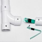
On the business end in the upper left corner, there is a 3/4″ PVC coupler into which a 3/4″ plug is inserted. Mounted on that plug is a ball mounted cold shoe. The boom was used with a Rode VideoMic in the cold shoe.
The telescoping section of the boom is made from lengths of thin walled 1″ and 3/4″ PVC pipe. It is important that the outer section be thin walled because 3/4″ PVC will not fit inside the normal schedule 40 or schedule 80 1″ PVC. The inner section can be whatever class of 3/4″ pipe that is handy. This photo shows the telescoping section in the collapsed position held by a super clamp.

This particular section is unpainted because it has not yet been built into anything yet. It is about 30 inches long in total, with the inner pipe being about 3 inches longer than the outer. This next photo shows the inner pipe extended to indicator marks about 4-5 inches from the bottom end of the inner pipe.

Here, the inner section is pulled farther out to show the friction producing element that keeps the whole shebang extended and in place where it is left. The purple rope is 3/16″ diameter rope from Home Depot.

The astute observer will notice in the photos above and below that the purple rope is frayed some on the right hand side. This would be due to the sharp edges on the holes through which the rope is threaded. (Note that this particular section was an early prototype of the telescoping PVC section.) The edges of the holes should have been rounded to prevent/minimize the fraying of the rope.

The rope is threaded through two sets of holes drilled through the 3/4″ section as show in the photo below. The rope exposed on the outside of pipe is about 2.5-3″ long. The pair of holes at the open end of the pipe should have been drilled closer to the end, about 3/4″ from the end.

Drilling those holes closer to the end side allows tying a tighter knot in the inside of the pipe to keep the rope loop as taught as possible. The photo below shows the square knot that was tied inside the pipe between the two holes at the end of the pipe.

Here’s another photo showing how deep inside the pipe the knot was. The rope is threaded straight through the holes farther back. The ends of the rope were inserted into the holes at the end of the pipe. Once the two ends are inside, the square knot is tied as tightly as possible. The rope should be cut a little long to allow for the length that gets taken up in the knot; longer ends will help in tying a tighter knot.

And that’s pretty much it. Rub the rope that’s exposed with wax from a sacrificial candle to give some lubrication. Then stuff the rope end of the 3/4″ pipe into the end of the 1″ thin walled pipe. If desired, mark the inner pipe so you know how far you can pull without yanking it out all the way out.
Now for a description of the home made clips that hold the completed boom to the tripod legs in the very first photo. Here are some close up photos of the two clips.


The upper clip consists of two lengths of 1″ thin walled PVC about 2 inches long. A lengthwise piece about 3/8″ wide was cut out of each length with tin snips. The corners were snipped as well to round them somewhat. Two holes were drilled in each piece. A zip tie was knotted with a half hitch (simple knot) such that the head was as close to the outside of the clip. The other end was threaded through another clip and snugged up as tightly as possible. The knot allows the two clips to rotate relative to each other. The weight of the boom hanging will keep the clips from causing any rattle.
The lower clip was made in the same way, but half of it is a threaded/slilp 1″ PVC coupling. The two holes were drilled in the slip section of the coupling so a mating coupling could be threaded into the fitting.
As can be seen, the bottom end of the boom has a 1″ male threaded end that threads into the clip. The threaded end was used on the boom enn because it was threaded into a weighted PVC pipe base that is not shown here.
Here are some ideas for as yet unimplemented/untested improvements on this telescoping assembly:
One way to keep from pulling the inner section out too far would be to not cut the rope off the spool when tying the rope onto the inner section. After tying, leave a length of rope somewhat longer than the 1″ outer section. The rope end can then be tied such that it keeps the inner section from pulling all the way out. Using rope to constrain the inner section allows later disassembly, if ever necessary.
Another way to keep the inner section from pulling all the way out would be to drill out a 1″ PVC end cap to the outer diameter of the 3/4″ pipe. This would be carefully glued to the end of the 1″ pipe after the inner section has been inserted. The disadvantage of using an end cap in this way would be that it is permanent.
The amount of friction of the telescoping inner pipe can be controlled by the length of exposed rope on the inner section. I.e., more rope will give more friction. Salt and adjust to taste…
About The Author
David Dicarlo is a portrait and event photographer based in Austin, Texas. You can watch his work at Sunday’s Child Snapshots.

Udi Tirosh
Udi Tirosh is an entrepreneur, photography inventor, journalist, educator, and writer based in Israel. With over 25 years of experience in the photo-video industry, Udi has built and sold several photography-related brands. Udi has a double degree in mass media communications and computer science.


Join the Discussion
DIYP Comment Policy
Be nice, be on-topic, no personal information or flames.
One response to “DIY: A Telescopic PVC Boom”
Thank you!