


How To Build An Automated Rail For Crazy Macro Shots for $150
Feb 2, 2016
Udi Tirosh
Udi Tirosh is an entrepreneur, photography inventor, journalist, educator, and writer based in Israel. With over 25 years of experience in the photo-video industry, Udi has built and sold several photography-related brands. Udi has a double degree in mass media communications and computer science.
Share:

Getting a good, in focus macro shot is not trivial. Even with a stopped down aperture, the depth of field is just too tiny, sometimes being less than half a millimeter. But usually, you want to shot open because you need every bit of light you can get, which makes it even worse.
The way to overcome this depth of field nightmare, is by shooting many photos, where each one has the focus slightly shifted, than stacking then together, and taking the focused bit from each one. You do this by mounting the camera on a slider and taking photo after photo after photo….
Or you can automate the process like pulsar124 and his Fast Stacker – a $150 solution for stacking macro shots. (Commercial version like the Stackshot only start at about $550, so if you have the time, this is quite a useful build).
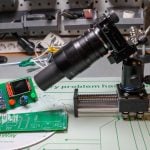
The core of this build is a Velbon Macro Rail ($114). The rail is connected to a stepper motor, which in turn is connected to an Arduino and a control box. (List of items can be found on Sergey’s page).
The source code is available on Sergey’s page as well.

I am pretty sure that Sergey is proud – the spec list is definitely comparable to top notch units (look at that 151-frames fly in the eyes and tell me I am wrong…)
- Maximum stacking depth: 55mm;
- Maximum framerate: 4 fps (or higher if your camera + flash can handle it; my Canon 50D can do up to 4 fps);
- Maximum speed: 5 mm/s;
- Accuracy: 2.5 microns;
- Total weight (the rail + motor unit + controller unit + battery unit + 8 AmazonBasics AA batteries): 1.28 kg;
- Maximum load: at least 1 kg, probably more;
- Startup time: 0.5s;
- Has 45 different functions.

This video has a full demo (35 minutes)
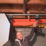
Here are some move views on that rail. Sergey estimates it takes a few days to build.


[Fast Stacker | pulsar124]

Udi Tirosh
Udi Tirosh is an entrepreneur, photography inventor, journalist, educator, and writer based in Israel. With over 25 years of experience in the photo-video industry, Udi has built and sold several photography-related brands. Udi has a double degree in mass media communications and computer science.
Related Posts
 Fast Stacker 2.0 is an automated focusing rail for macro photos you can build yourself for $180
 This Arduino-powered DIY macro rail helps you shoot perfect stacked macro shots every time
 Create An Automated Macro Rail For Image Stacking
 Build your own DIY ceiling mounted lighting rail system for under $100
Join the Discussion
DIYP Comment Policy
Be nice, be on-topic, no personal information or flames.
8 responses to “How To Build An Automated Rail For Crazy Macro Shots for $150”
Very cool
Thank you, Sergey!!
This is impressive! I wonder how it could be adapted to film photography. I have Canon A-1 and F-1N with the Canon Auto Bellows and the Canon Macrophoto 20mm f3.5 which provides magnification of 3.92X-10.72X. I have the respective motor drives which have a remote trigger; but using the motor drive with the bellows, I have to shoot in portrait mode instead of landscape.
It should work from a technical point – as long as your camera has a remote shutter connector – but film cameras are not well suited for extreme macro focus stacking. At magnification 4:1 you need something like 100 photos to cover a reasonable DoF (comparable to the frame width). You can’t do it in one go with film, plus it’ll take a long time to scan all those shots.
That’s what I thought. With 100 shots needed, I would have to load the camera three times and that would change the setup.
UPDATE [03/03/2016]: New version (s1.14) of my focusing rail software was released. The important new feature is the support for Full Resolution Silent Picture (electronic shutter; only Canon cameras), with or without an external flash. Also some bug fixes. The rail was tested at magnification 10:1 (5 um steps), and it works very well (see https://www.flickr.com/photos/99745838@N03/25384340795).
Full details:
http://pulsar124.wikia.com/wiki/Whats_new
Hello! Awesome video! I am new to focus stacking but what I am curious about is your lens set up. I see extension tubes but on the front end, that looks like something special. What is your lens set up? Thank you for all your work putting this together!
Hello How do I contact you on WhatsApp or any other means of communication?